pullo
-
Posts
464 -
Joined
-
Last visited
-
Days Won
2
Content Type
Profiles
Forums
Downloads
Store
eMastercam Wiki
Blogs
Gallery
Events
Everything posted by pullo
-
Has anybody else set up a 5 ax post for the new DMU-60 EVO
pullo replied to pullo's topic in Industrial Forum
So many answers I have to give here.... Actually , I was hoping to get an answer from my esteemed colleagues Greg Williams : "this value of -150 gets added to every C axis output." . This is the definition of a shift . We are of course talking of a rotary shift. If you mean that I could get the shift done on the control , yes I could do that probably with a Cycle Def 7.0 Datum Shift , C-150 command . The result would be the same. However , if for some reason the operator would negate the command we'd get a crash... mkd : yes it is a Heidenhain control on this machine. I was referring to machining when RTCP is turned on (M128). The plane spatial/Cycle 19 works fine , as I can sidestep the issue of outputting the B-angle by outputting the A and C angles. The machine will calculate the right B angle based on A . JLW: I will slam dunk this probably today. I will measure the position of a hole on the outer axis of the the table ( for max angular precision) in 3-axis mode and the I will position a gauge above the hole in RTCP /M128 /5-axis mode and see if the positions aline . I realize this is a reverse engineering approach, but it's one that will get me close to the end result and that will give me time to ask around/figure it out , whilst the customer is chugging away on his new DMU-60 evo -
Has anybody else set up a 5 ax post for the new DMU-60 EVO
pullo replied to pullo's topic in Industrial Forum
Seems like gcode is responsible for the 670 evo . It is , I say again DMU 60 evo. Gracjan -
Has anybody else set up a 5 ax post for the new DMU-60 EVO
pullo replied to pullo's topic in Industrial Forum
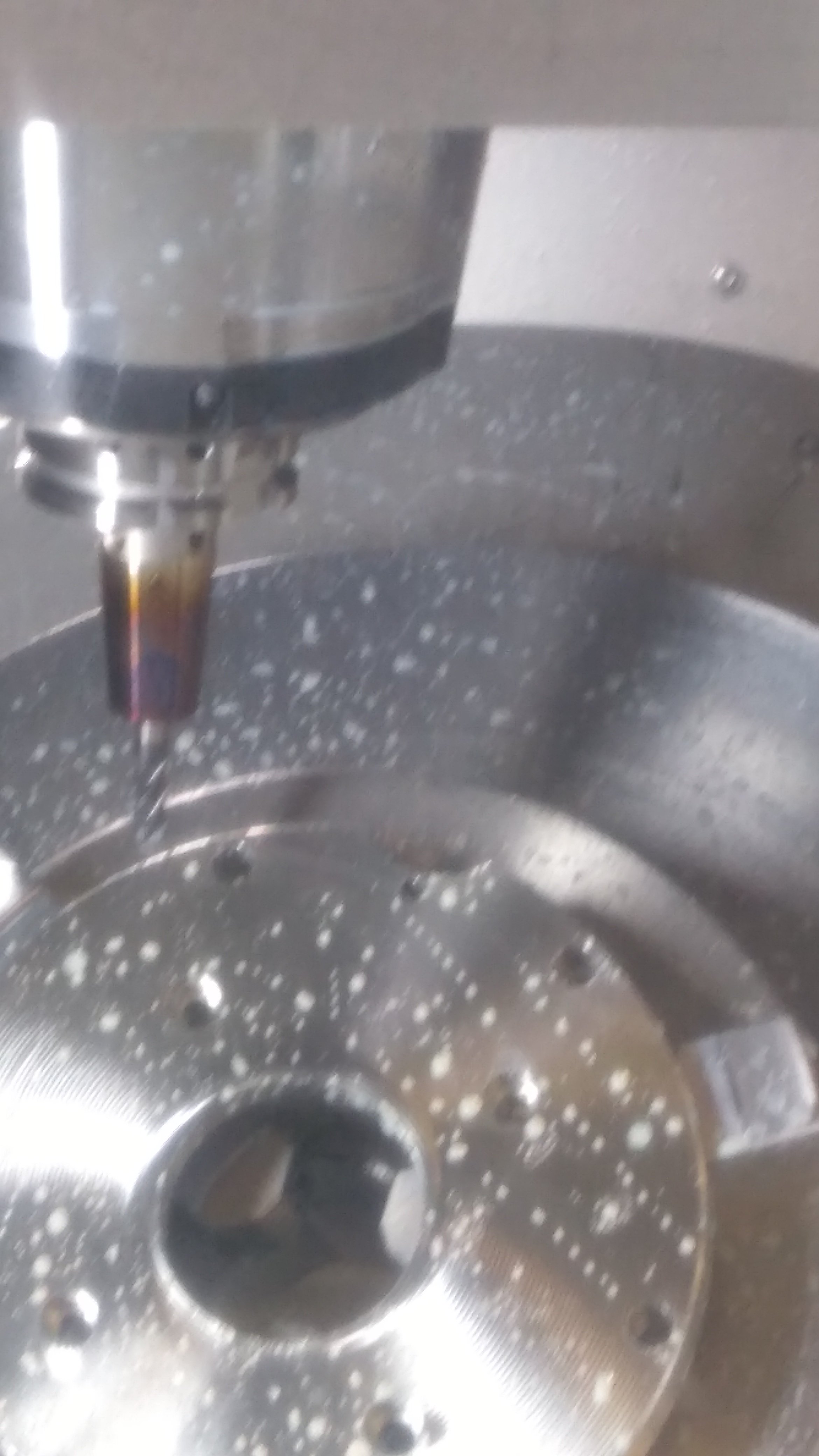
I just realized that the heading is WRONG IT SHOULD BE DMU 60 EVO well anyways back to the subject... and this is the result on the machine , or in laymen terms , all is fine. the axis of the tool intersects the axis of the cental hole of the part , etc..... Gracjan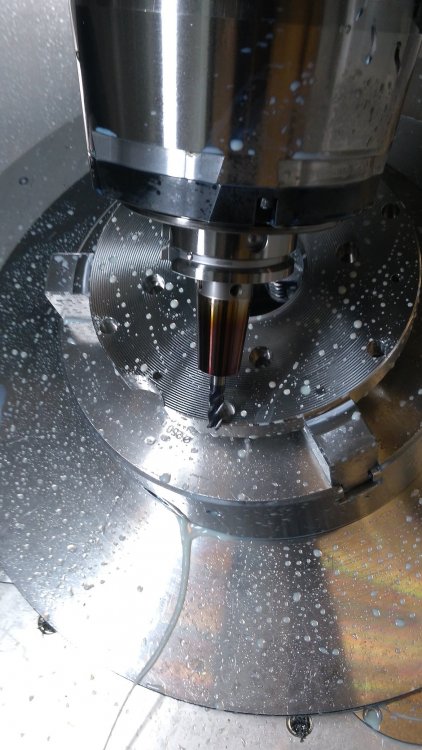
-
Has anybody else set up a 5 ax post for the new DMU-60 EVO
pullo replied to pullo's topic in Industrial Forum
So , in order for a post to work properly for this machine ,these vectors have to be input : 1. The vector of the spindle 0,0,1 2. The vector of the variable rot. axis (C) 0,0,1 3. For my machine ( these values will slightly differ from machine to machine ) 0.5849.... , -.5735..., 0.5735... which is 44.6 degs from TOP and 44.6 degs from FRONT with these values I tried to machine the chamfer on the part , the axis of the tool pointing towards the center and this is what I got ( a totally senseless result) After manually trying out a few values , I came to the conclusion that a Shift in the C-axis of -150 was more or less what I am looking for (this value of -150 gets added to every C axis output. With the shiftc of 150 in my post , this is what I saw on the machine :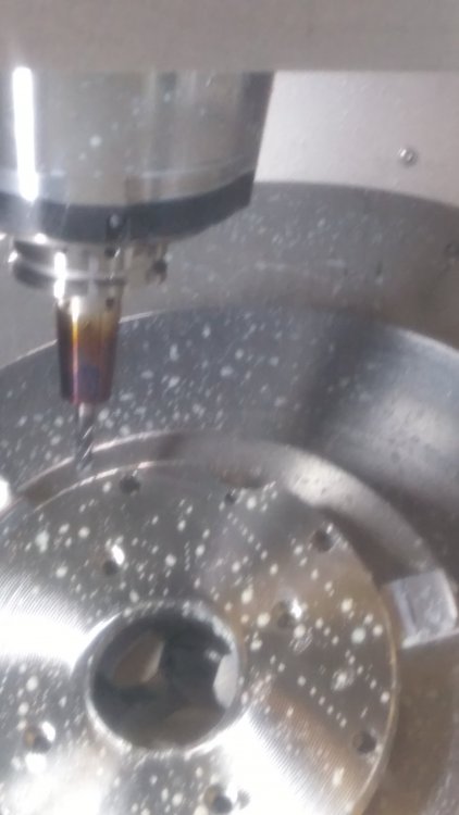
-
I have right now ascertained , that I have to use a shift of "circa" -150 degs on the C-axis for the machining to look "right" , so that is the ballpark , but what is the precise value, ? Gracjan
-
if the arcs are driving a solid , once in a while , not always propagation will kill Mcam when regenning the solid..... Gracjan
-
ok I'll report it to gcode. It works for me , but I was also the one who put the link there, deleted the file and asked to make the link work again.... Gracjan
-
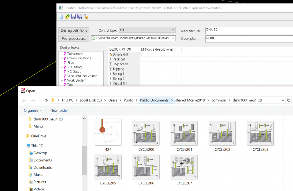
The graphic file was a .bmp, 256 color, the size 266x241 pixels Gracjan

-
Never mind , I figured it out Gracjan
-
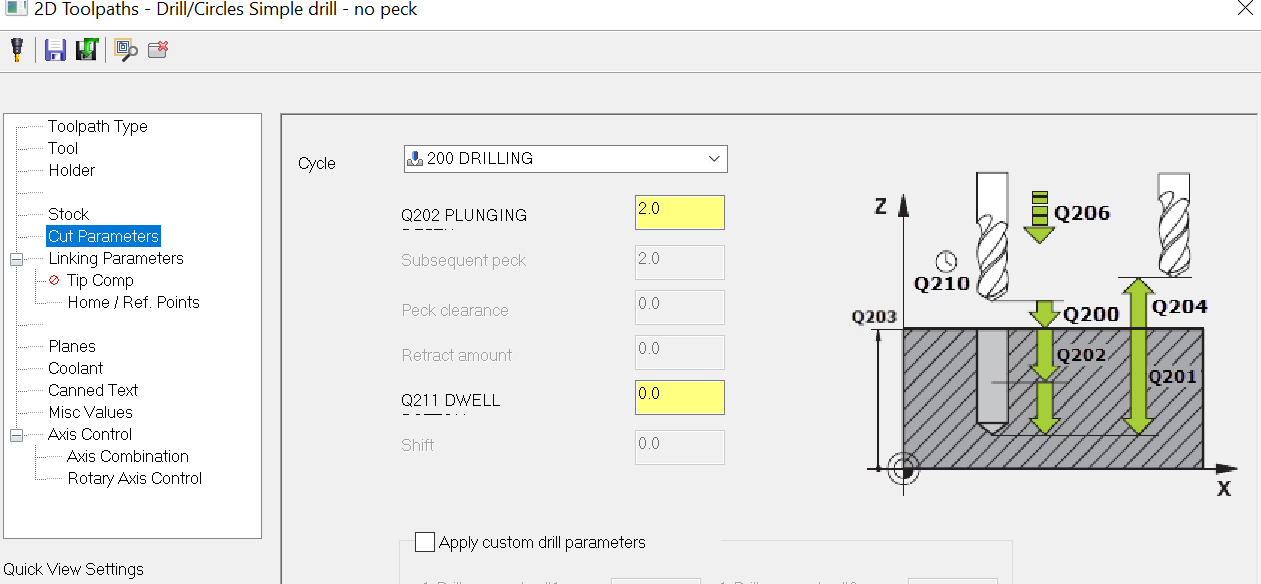
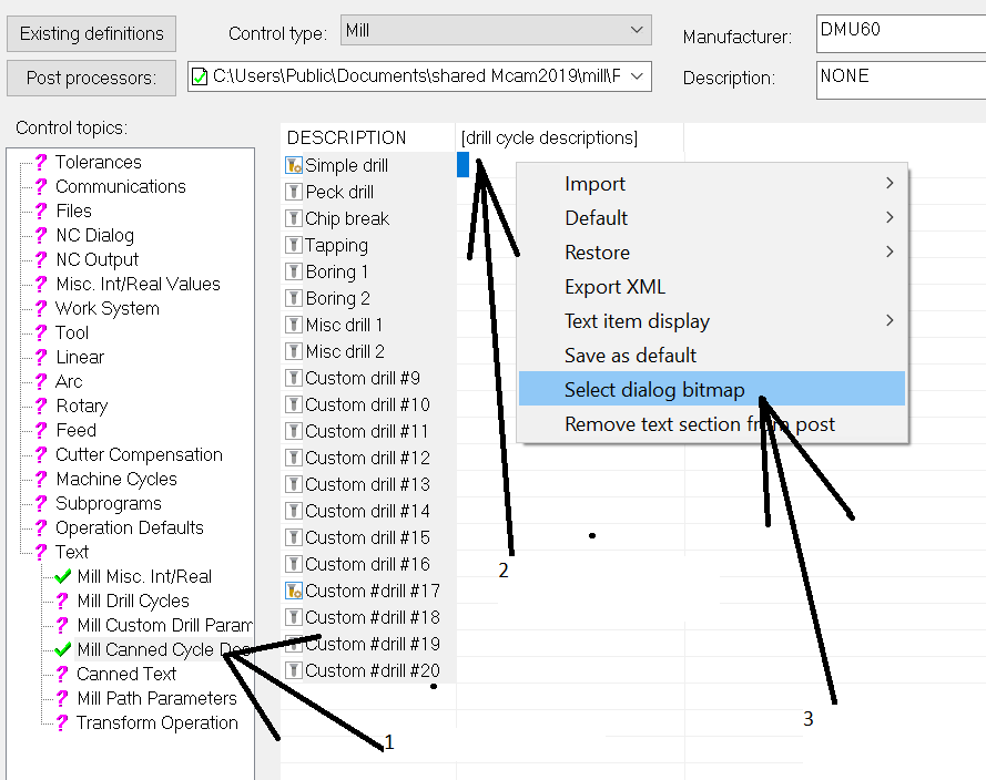
Could someone shed more light on how to substitute the graphics shown in drilling cycles ? It involves putting them in the \common subdirectory under \shared Mcam2019 .... Gracjan
-
Just tried an upload from the first comment in this thread . It looks like it's working. Gracjan
-
A guy who did a post for an 80 evo had identical values for his B axis vector, so it's no coincidence... Gracjan
-
The older machines were 45 degs, the new ones are slightly off that round value. Gracjan
-
AMC Nitro , we have yet to find out the control on your machine...... Also the other thing that we are all guessing here , but have not been told by You is , WHERE DOES THIS M30 pop up?. In our opinion you should only have ONE M30 in your program and that is at the literally very end of your program . The M30 is the same as in walkie talkie language "over and out" . Usually there is silence after that . The most you want here is an "over" utterance. That would be an "M2". Since you seem to have a problem that would suggest that the M30 is issued in other places of the program other than the very end. SO get rid of all these M30 codes , because they seem to be used incorrectly and maybe leave the very last one , just before you hit the percent sign if your program is Fanuc styled.... But this is all guess work , since we lack info from You....
-
There seems to be a very elegant solution to avoiding programming of tapered shapes . Its a G87 which introduces a constant radius fillet instead of a tapered one. This feature has not been implemented on the posts supplied by CNC, but has anybody successfully implemented this on their own ? If so I'd be very glad to find out more about this . Gracjan
-
I usually do this with parallel, works like swarf in the end ... A long time ago The Module Works 7 toolpath types were just tweaked into applications and given a new name. Swarf would revert to Parallel to Multiple curves... Gracjan
-
I remarked also that 2020 TP5 ( there is nothing else new at the moment ,although the familiar questionnaire signaling a new version has already been sent did not yet correct, so Chally 72 , what 2020 version are you on ? But if Aaron says it's now OK in 2020 that's good enough for me... Gracjan
-
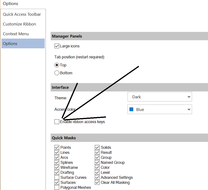
A little bit beside the point , but I noticed from your first pic that you have those little numbers appearing next to your ribbon functions . You can turn that off now in 2019 from "Customize the Ribbon...." As for the problem at hand , I tried tweaking almost everything, but it just won't regen properly. Also the problem persists in 2020. You'll have to send it to QC... Gracjan

-
It has now been established many times that when it comes to the names of the Intel chips , they have not much of input in the way of speed. Only clock speed counts. I would also suggest you check out the Benchmark 3.0 thread , as that is the most up to date place about Mastercam speed . Pullo
-
If the line is in the Y direction , you will never be able to extend it in the X Chachacha Gracjan
-
Yes , What I do that is similar is I let the machine build up spindle speed after a tool change , so the time the machine is idle is a linear function of revs. But for you it would be adding a hard coded wait command (whatever it is on your control ) if the coolant is turned on. Now it's down to if you know how to modify posts... Gracjan
-
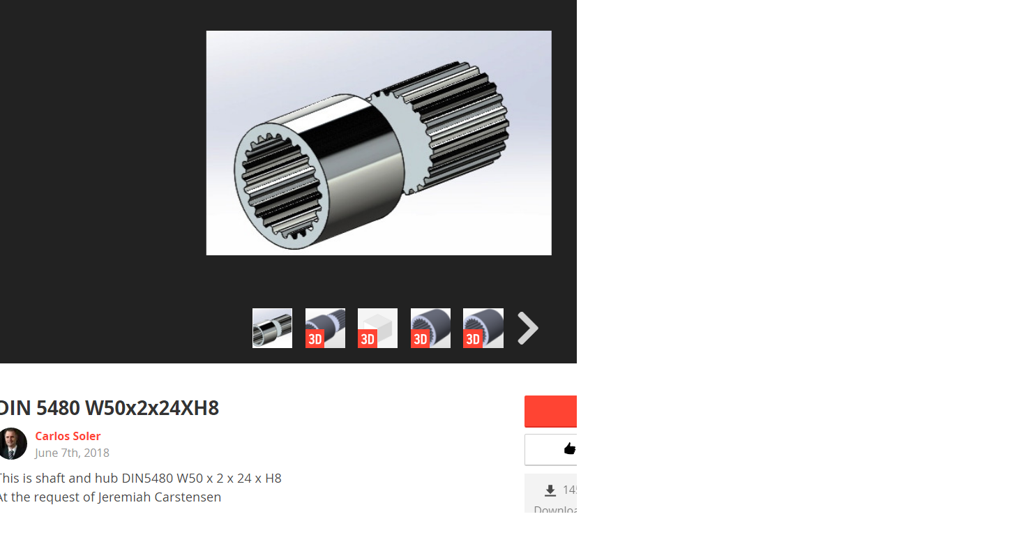
It's the "spline "word here that is misleading to someone not producing this type of stuff. I was used to the definition of a Spline as a "Special Line " , curves used to draw ship hulls . Wikipedia : Splines are ridges or teeth on a drive shaft that mesh with grooves in a mating piece and ... External splines may be broached, shaped (for example on a gear shaping machine), milled, hobbed, rolled, ground or extruded. There are fewer ... Gracjan
-
The term "Conventional cutting" comes from the times when a things were run using gears. Conventional cutting would used to zero out the lags due to gear teeth gap. Climb cutting will usually cut less material than it is supposed to as tool will bend away from the cutting material . Conventional cutting will usually cut more material than it is supposed to as the tool tends to bend into the cutting material. So climb cutting is the more preferred method . There is however a time when conventional cutting is useful. If you are trying to cut a hole or an opening and it has to be very precise, you will very soon realize that a say D10 hole which is 20 mm deep and is cut with an 8 mm mill will be slightly conical . Not much , maybe 0.015 per side , but that is enough for a D10 H7 cylinder to become immovable. This is the time to machine this hole (after it has been cut using climb cutting ) using conventional milling that will cut the deep part to be more vertical or techincally vertical. Gracjan
-

-
SInce you brought this up , mind explaining what all that (at first sight ) incomprehensible stuff means ? Internal spline ? What's an external spline then ? etc.... Gracjan