Rob - In-House
-
Posts
30 -
Joined
-
Last visited
Content Type
Profiles
Forums
Downloads
Store
eMastercam Wiki
Blogs
Gallery
Events
Everything posted by Rob - In-House
-
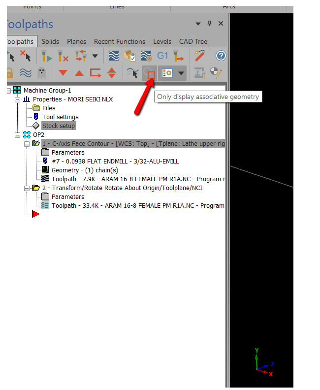
This is from the Mastecam help menu.
-
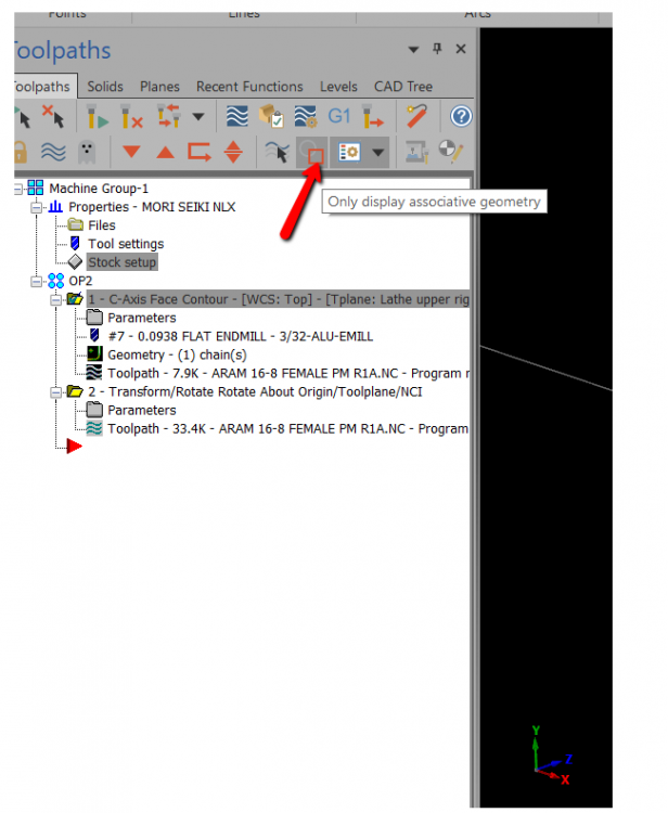
pvtJoker Turn off the selection button to only display associative geometry.
-
Hien Le Have you tried to use different browsers ? I had no issues downloading the files with Chrome or IE.
-
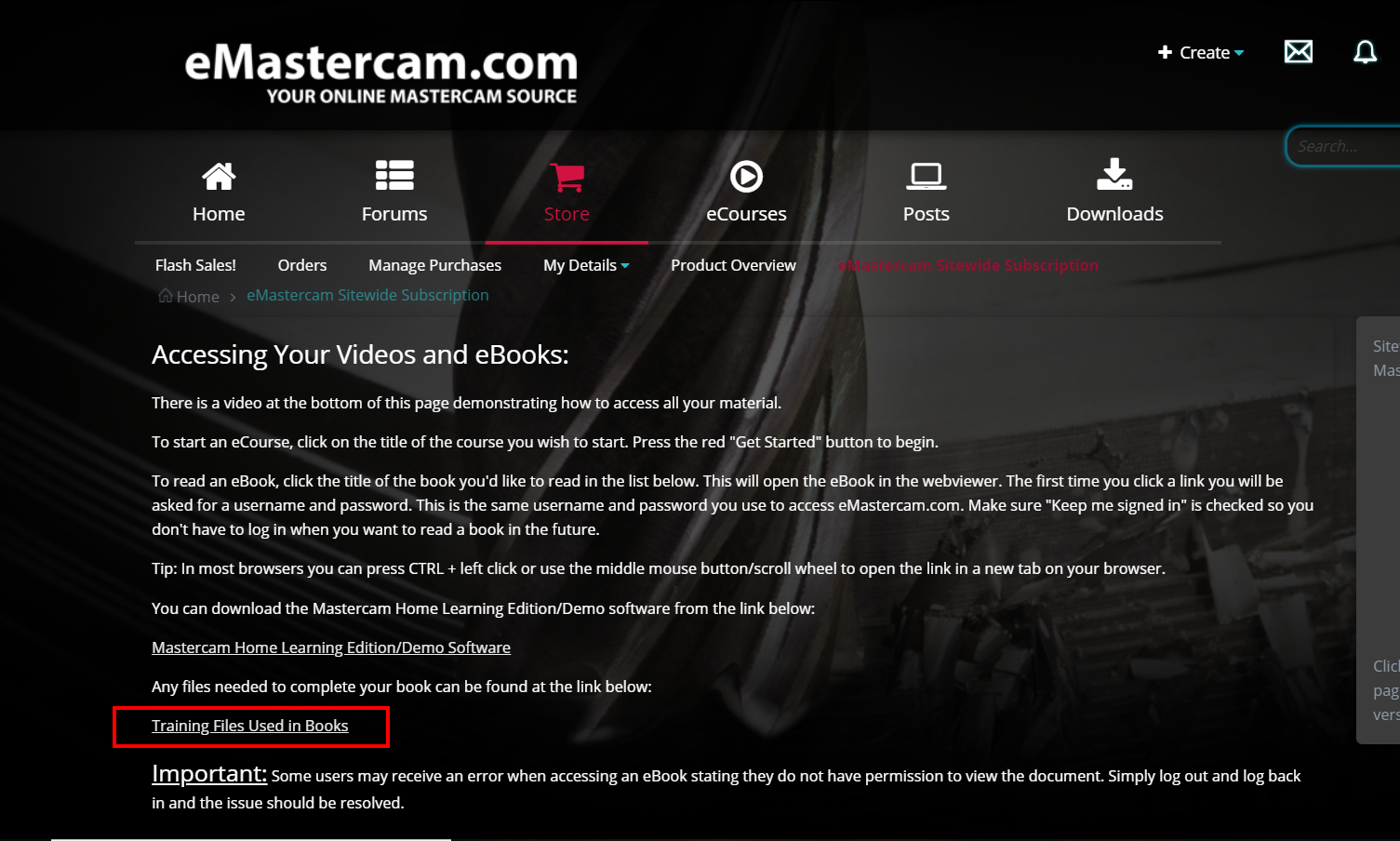
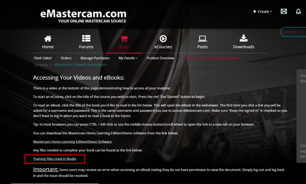
nolongat, You can find the all the download files when you are accessing the ecourse.
-
Rick. You can edit the short cut for your HLE to disable the hardware acceleration . The document attached shows how to edit it. HLE Hardware acceration.pdf
-
razorone Unfortunately the HLE expires 24 months after release. The only current versions available are 2019 or 2020.
-
Changing Thru Coolant Code
Rob - In-House replied to JB7280's topic in Post Processor Development Forum
JB7280, You should be able to change this in the machine definitions under the general machine parameters tab. See the video I have attached.- 1 reply
-
- 1
-

-
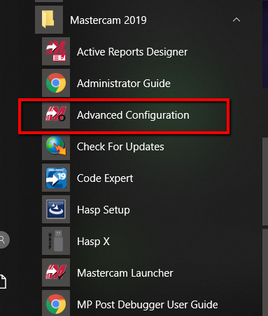
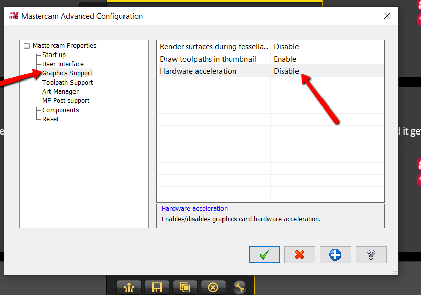
Murdock, Might be the graphic card. Onboard graphic cards are not supported by Mastercam. You could try to disable the hardware acceleration in the advanced configurations. Open the mastercam folder from the windows start menu.
-
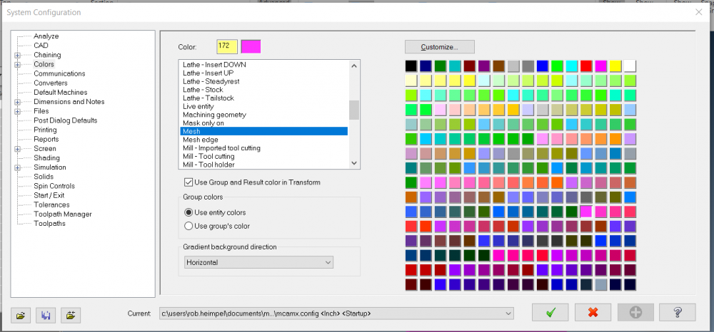
Grimes, In the view tab under grid you have activated the snap to grid. To set a default color for the stl file set the "mesh" color to what you want the file to open with.

-
Mastercam University - Help needed from a student
Rob - In-House replied to MatthewMachinist's topic in Educational Forum
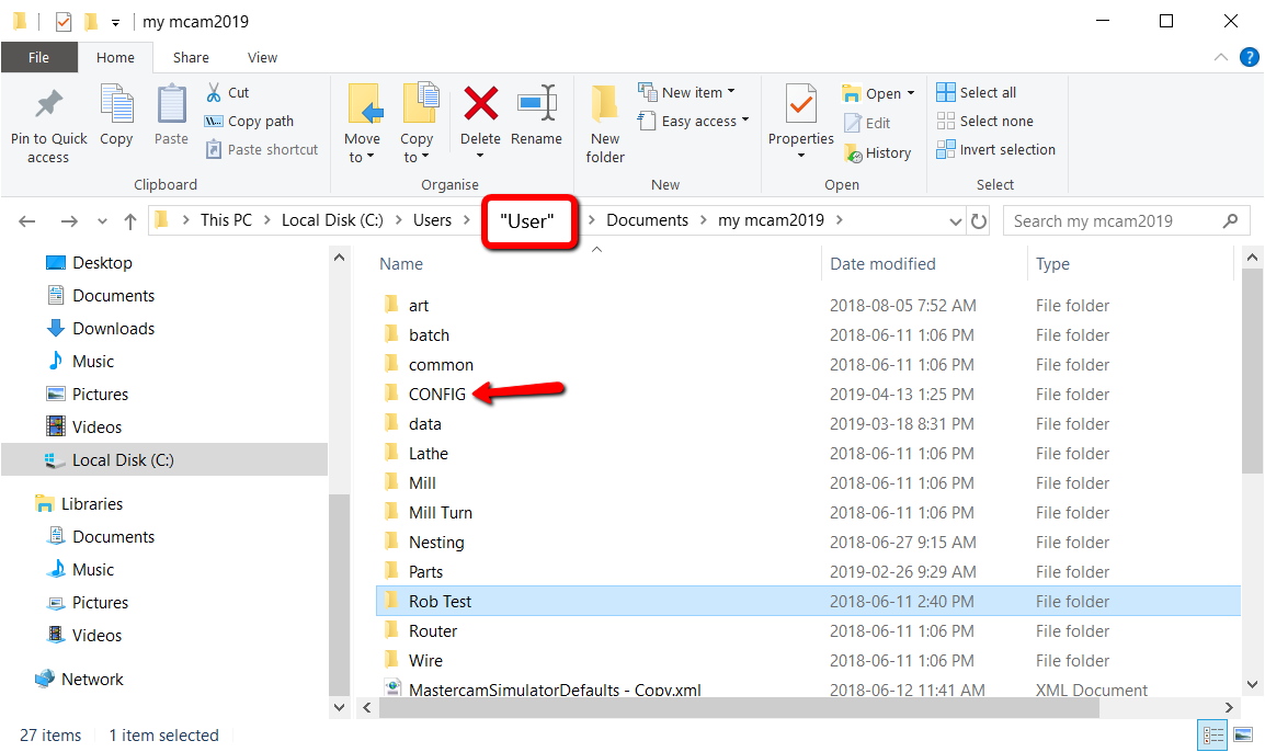
MathewMachinist I did test your file and did not have any issue creating the lines normal. It may be an issue with you have Mastercam set up. Try resetting Mastercam back to the defaults.Close Mastercam, navigate to the folder shown (yours will probably show my mcam2019HLE) and rename the config folder to config.old. Mastercam will recreate this folder with the default settings when you restart.
-
Drawing Layout and Exporting
Rob - In-House replied to MatthewMachinist's topic in Educational Forum
I believe you are creating the Mastercam file in metric and the template you are using is imperial. Try to create the file in imperial or don't use the template. To create a PDF of the layout select print and choose PDF converter as your printer. You may need to add the PDF printer in window setup.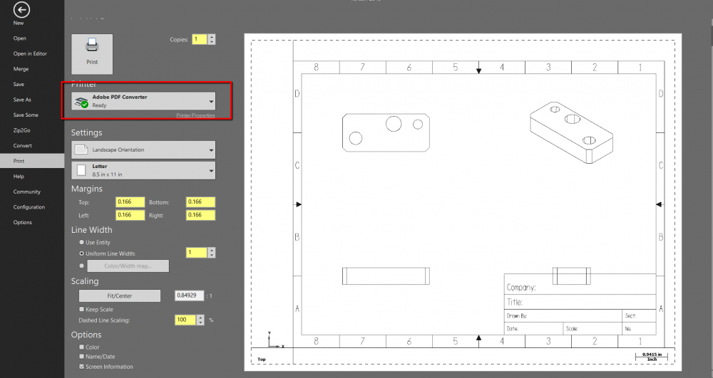
-
Lazarusman, Check out the links I have attached. We have some great resources on our website with more to come. https://www.inhousesolutions.com/education/resources-for-education/ https://www.youtube.com/user/MastercamCadCam
-
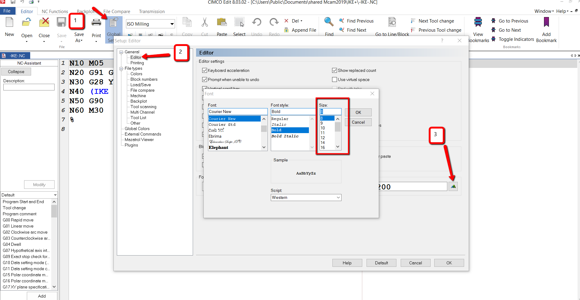
junky programmer, It's in the global settings of the editor.

-
jayz32926, There is nothing in the zip file. Can you try to post it again?
-
mastercamnoob, I assume you are referring to the manager tab that is normally on the left side of the screen. Is it just not pinned into position and is set off the screen. Left click and hold the top of the manager and drag it to the desired side of the screen. Double click the top of the manager to lock it to that side. See the video below for more tips. https://www.inhousesolutions.com/2016/08/toolpathssolids-manager-displayhide-mastercam-2017/
-
Mastercam University - Help needed from a student
Rob - In-House replied to MatthewMachinist's topic in Educational Forum
Matthew, I am still not sure why you are unable to set the line normal to the center of the circle. Could you post the file and I could have a look at it? -
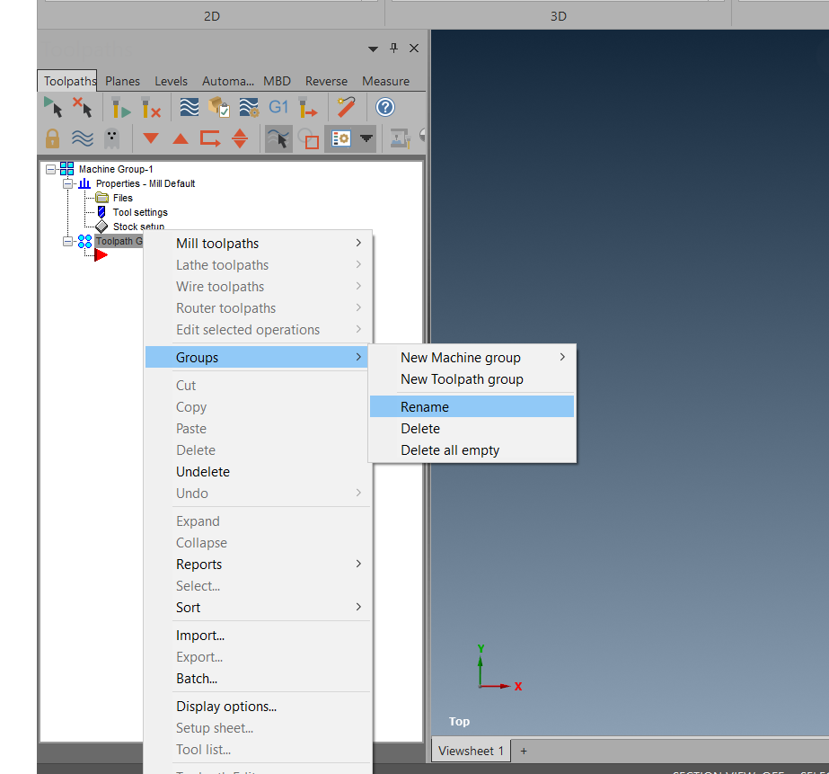
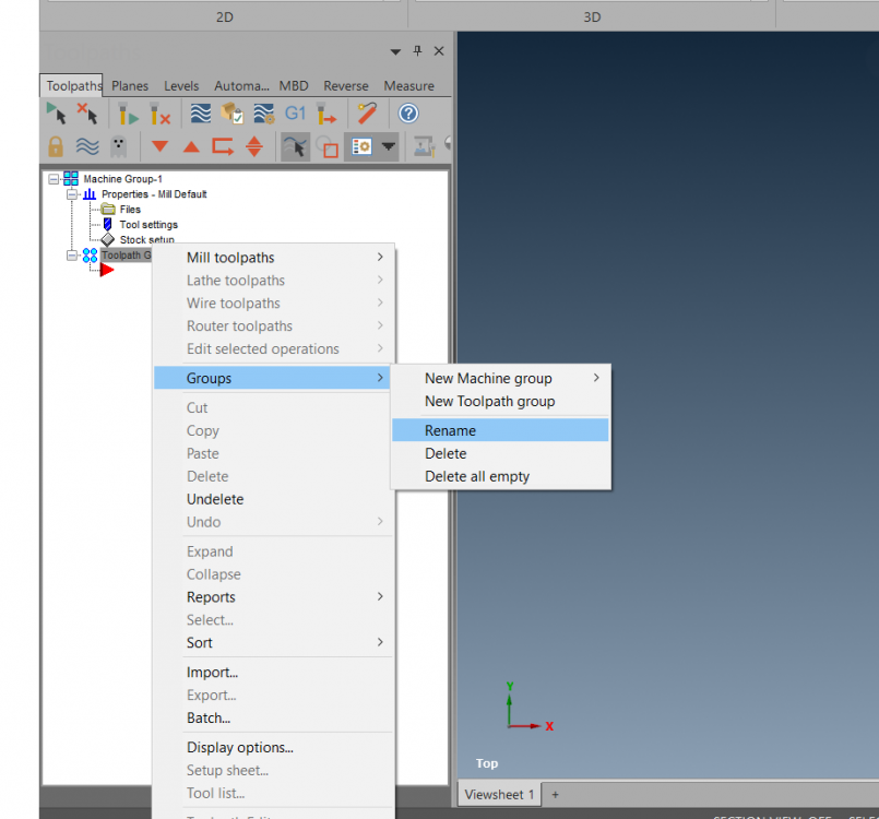
Looks like you just renamed your "Machine Group" and your "Toolpath Group" Right click on the groups and rename them.
-
Mastercam University - Help needed from a student
Rob - In-House replied to MatthewMachinist's topic in Educational Forum
MatthewMachinist, Looking at the picture you added it looks like you are selecting the wrong face when creating the line normal. In the picture I have attached you can see the inside face that the holes are set onto is the one you should be selecting. The front face of the arm and the inside slot face are not parallel . By selecting front face the line is going to be on a different normal then the hole you are trying create the line on. Levels are used as a way to reduce screen clutter or separate geometry. You are able to copy or move geometry to a different level. These level can then be turned off to remove the geometry from the screen and back on again when needed. Imagine if you have a part that has hundreds of features it would get very cluttered if everything was left on one level and could not be turned off.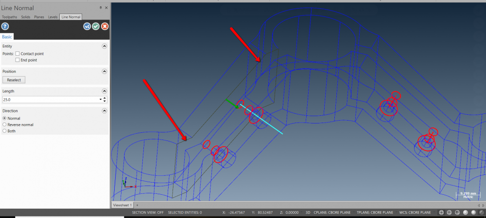
-
Mastercam Lathe Diameter or Radius Mode
Rob - In-House replied to gkhneyplr's topic in Woodworking Forum
gkhneyplr, What is the post you are using? I believe its going to be a switch in the post. dia_mult : 2 #Multiplier for output on X axis (Neg. switches sign of X) Changing the 2 to a 1 will output radius. Be sure to back up your post before making any changes to avoid loss of data. -
Faceted surface when machining surface
Rob - In-House replied to GioOne's topic in Educational Forum
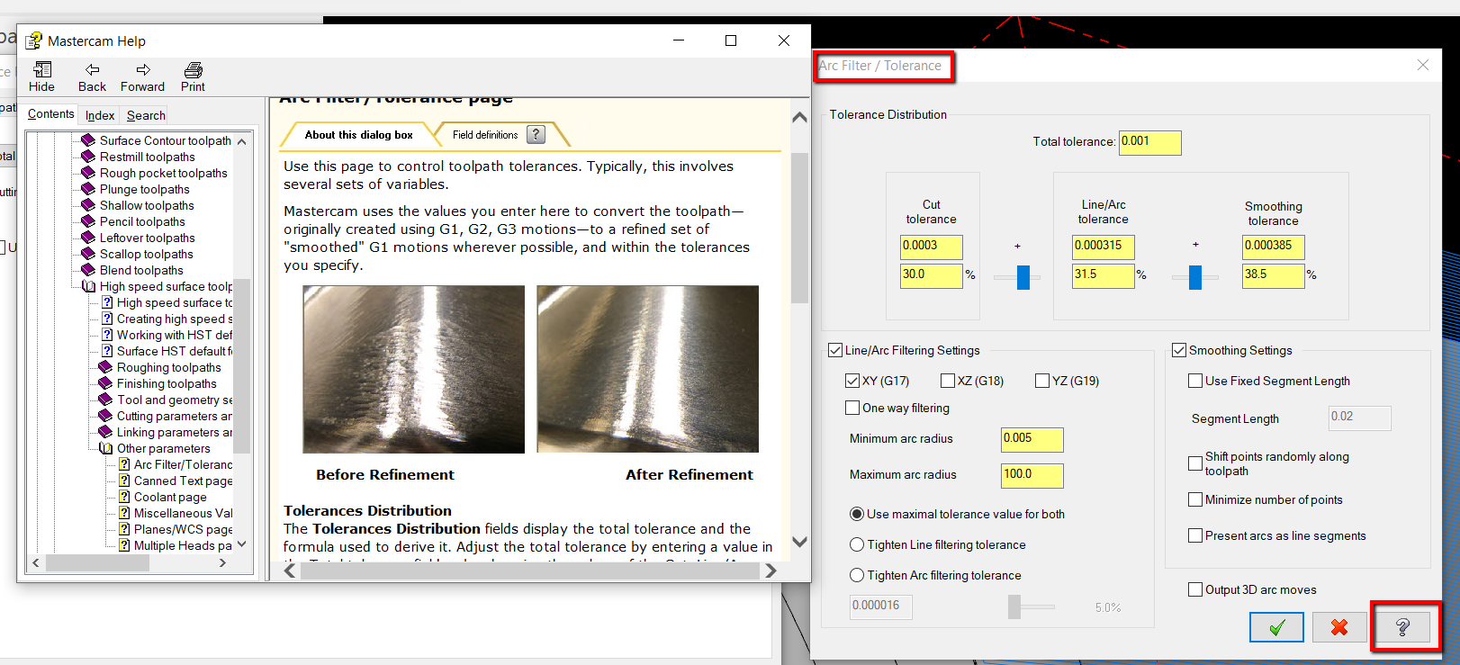
The post is going to change them to linear moves. By selecting the total tolerance function you are able to adjust the arc filtering to create a smother surface. Once you are in this function select the help button for a more detailed explanation of the filtering process.
-
Changing colors in Code Expert
Rob - In-House replied to So not a Guru's topic in Post Processor Development Forum
So Not a Guru I believe the option you are looking for is in the Interface options.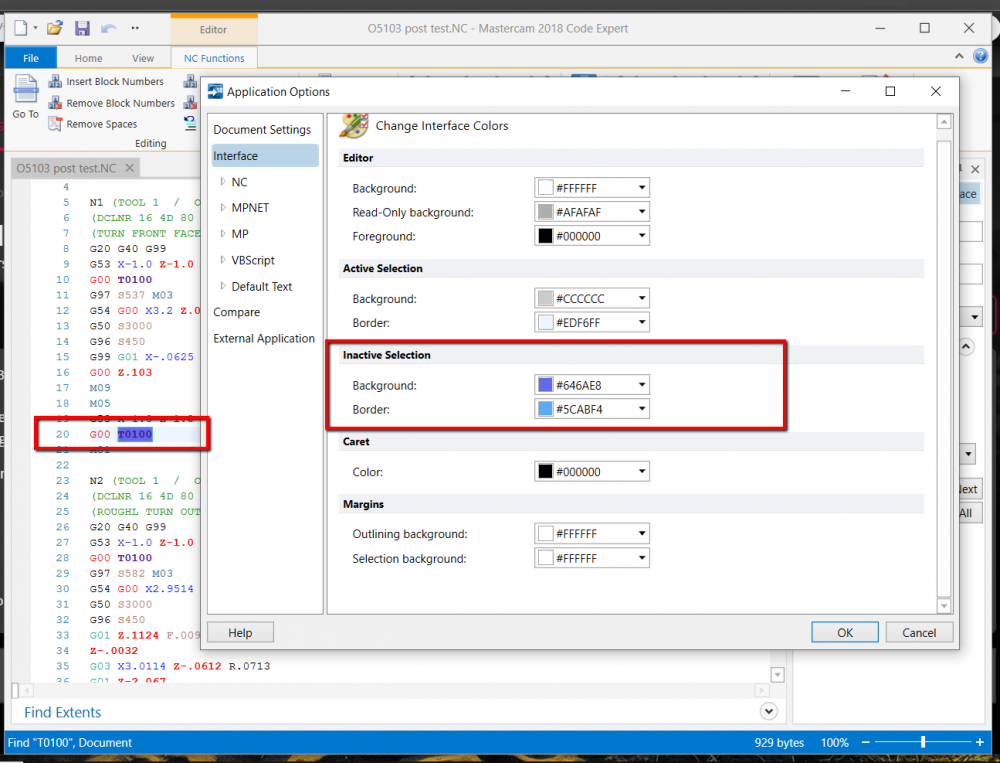
-
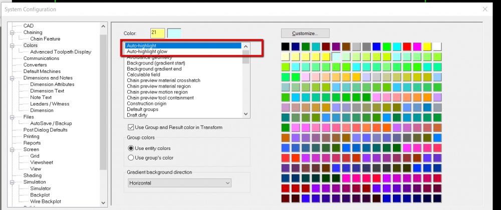
carryinwood These colors can be changed in the System Configuration. Change the auto highlight and /or the auto-highlight glow to the color you prefer.
-
Are you able to post a zip2go of the file?
-
Cimco DNC transfer tab lost
Rob - In-House replied to SlaveCam's topic in Machining, Tools, Cutting & Probing
SlaveCam In the global setup of Cimco make sure the "Disable DNC/Serial communication" is not selected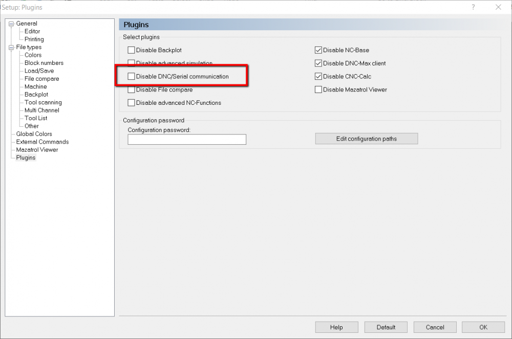
-
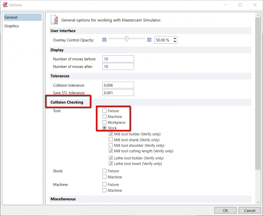
PiotrN When you are in the verify feature of Mastercam 2019 the collision checking with fixture option can be found by selecting. File> Options> General.
- 1 reply
-
- 1
-