JB7280
-
Posts
996 -
Joined
-
Last visited
-
Days Won
8
Content Type
Profiles
Forums
Downloads
Store
eMastercam Wiki
Blogs
Gallery
Events
Everything posted by JB7280
-
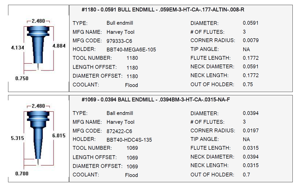
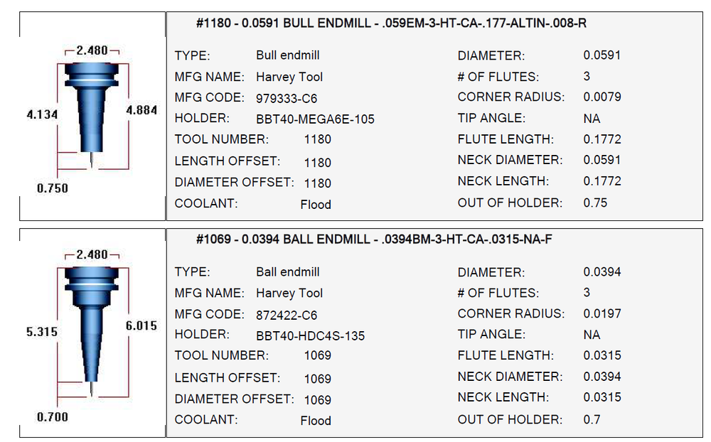
I'm trying to do some deburring with a lollipop mill. But for some reason it doesn't seem to be recognizing the cutting edge past 180deg. Is there something special I need to do for it to recognize the full tool?
-
From the few different models I've seen, it looks like they're all made at the same place. Big Daisowa, Redline Tools, and Haas fans all look identical, side by side.
-
If you liked this one, you should try the flip out style. MUCH more force.
-
Our Yasda came with one of these, and we found that it really doesn't move much air at all compared to the folding fans.
-
Our Active Reports Setup sheets print like this. Is there any advantage of using Varco Reports over Active Reports?
-
I use them on all types of materials, steels included. I bought the large one from Redline tools, but they're all basically identical. As @Leon82 said, the center doesn't move much air so you have to "face" using the outsides. I have a subprogram that just does a quick, general pass. But for more specific chip clearing you can just use a facing toolpath. I dunno if they all do, but mine also has a center hole that can be used as a TSC jet, if theres stubborn areas.
-
I use this. Fixture Tracking Macro.pdf
-

Tips on dynamic facing toolpath - single direction
JB7280 replied to ThickChips's topic in Industrial Forum
That's what I would do, personally. But it sounds like he has some restrictions with the cut direction. -
Tips on dynamic facing toolpath - single direction
JB7280 replied to ThickChips's topic in Industrial Forum
I think you might have to make multiple facing operations, with appropriately sized boundaries. I would personally use an Optirest toolpath, but it seems that your workholding limits that. For the record, I'm not able to download the file at the moment, so there may be a better way. -
Hopefully you don't mind me linking to your Youtube videos Colin.
-
Colin's Youtube videos.
-
Best Extended Reach Tools for Milling?
JB7280 replied to [email protected]'s topic in Industrial Forum
I agree with you on this, regarding finish, but how do you get the heavy chipload AND a straight wall (minimum deflection)? Everytime I try, I have to take a spring pass, which results in a less desirable finish. -
Do you guys drill out corners where applicable
JB7280 replied to lowcountrycamo's topic in Industrial Forum
I'm not familiar with Mazak Contour control. Is that similar to IPC on a Matsuura? -
Do you guys drill out corners where applicable
JB7280 replied to lowcountrycamo's topic in Industrial Forum
Hopefully this doesn't hijack the topic, but I feel like it's on the same subject. Do any of you guy use the corner slowdown function in the arc filter section? I do a lot of deep(ish) pockets. Nothing crazy, but 6-8xD, and always seems to require a couple spring passes to nail the corner rads. -
This is what I ended up doing, I'm just not sure why it wouldn't let me do it the way I've done it so many times. Yes, all of the operations referenced in the stock model are clean. Everything looked good in verify, as I ended up using verify to generate an STL. .001 initial shape tolerance, .005 Path tolerance, .001 tool shape tolerance. Why am I using these numbers in particular? No idea. But they're the same tolerances I've used for a long long time. I found that too big was causing issues when using them for Opti-Rest toolpaths.
-
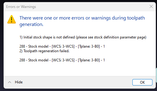
I am trying to generate a stock model, so I can create a mesh, or stl for my next operation, but for some reason I cannot get a stock model to generate. For initial stock shape I am choosing the Pmesh of the model for Op 3's stock. Then I am choosing all of the toolpath in Op 3, and I get this response.
-
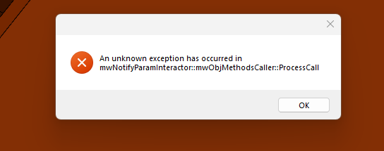
I keep getting this error message when choosing geometry for a 5x deburr toolpath. Anyone seen this before? Once I get it, I have to shutdown before I can pick any more geometry.
-
I am, but maybe not properly? I'll check that video out. Thank you!
-
Do any of you guys have suggestions for cleaning up, or "trimming the fat" from optirest toolpaths? I can't share the file I'm working on, but it seems to make lots of unnecessary cuts where it's taking very little material, if any. At this stage I'm really just trying to get material out, and not too concerned about getting terribly close to shape. For reference, I'm using a 2" indexable tool from Ingersoll with a .062" corner rad. I have my cutting parameters set to 60" stepover, .350" step up and down. I had read that setting stepup and stepdown the same will look for only the flats, but it doesn't seem to be doing that on my part. It still seems to be finding angled walls and trying to generate them.
-
Is this something I should submit to QC?
-
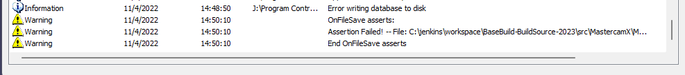
I did notice this in the event log. No idea whagt C:/Jenkins is. It's certainly nothing on my PC.
-
I've tried saving to the path I normally save to on the server, and also tried saving to the desktop. A coworker said he's been having the same problem since we updated to 2023.
-
Trying to save my file, and I get "error writing database to disk" wth?? Disk I'm saving it to is connected, and not full.
-
Thank you! I'll play around with this tomorrow
-
A coworker of mine who has been using mastercam for quite a long time says he does this, and almost never drives toolpaths off of solid. Only wire and surfaces. But wouldn't this leave you with lots and lots of surfaces? Are they more or less "bulky" than solids, when it comes to resources and file size? I've got quite a bit of Optirough toolpaths on this part, and it seems like using surfaces would be much more cumbersome. But maybe I'm just not doing it right Do you usually output the entire part as surfaces? or only what you need?