All Activity
- Today
-
 Masrouser joined the community
 -
 Mohamad Alassad joined the community
 - Yesterday
-
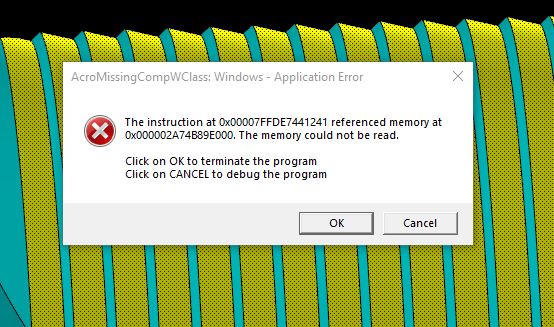
It's likely related to setup sheets that use a pdf reader, Here is a link to a thread on adobe about solving this, Solved: Acromissingcompwclass: AcroRD32.exe Application er... - Adobe Community - 8849028 You could also try changing the default program for opening pdfs
-
Thought #1 are you running One Drive on this PC? Thought #2 Both of these errors are Adobe Acrobat errors It's pretty weird they should be popping up during a Mastercam session Do you have Acrobat open??
-
I have been getting these and other Application Errors while in Mastercam, at this point no other programs are getting these. It shuts me down when they pop up. Any idea what may be causing this? I did reach out to our reseller and they are not familiar with them. It's pretty frustrating and I am hoping this is not an underlying issue that could wind up being pretty bad. I searched the internet but I'm not real certain what I am looking at, I'm not a applicationscomputer guy by any means Thanks in advance for any input.
WINDOWS-APPLICATIONERROR4-25-24.JPG.1189529aa06e0e41f527469641b02587.JPG)
-
 Thanks Colin! I actually did stumble on the goldmine of youtube videos you have posted there, and let me just say thank you for putting that info out there. I haven't made it through all the content yet, but the videos I watched so far were super helpful. I will also try to start assigning my work offsets by plane. I haven't tried that before, but I like that it might make things a little more foolproof.
 -
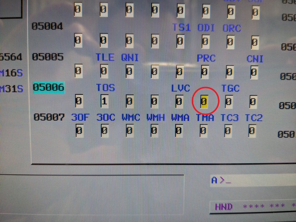
I tried adding all three values (XY & Z) on the G43.4 line but got weird undesired motion. I tried your second suggestion of using G43 inside the G68.2 call and that seemed to work. I tried it without changing the 5006 parameter and didn't get any Z motion with the G49. Is this the parameter I should change?
-
Sorry, misinterpretation on my end. You weren't finding an issue with the original question, you were providing a more in depth explanation to the provided solution. Thank you sir, this is much appreciated.
-

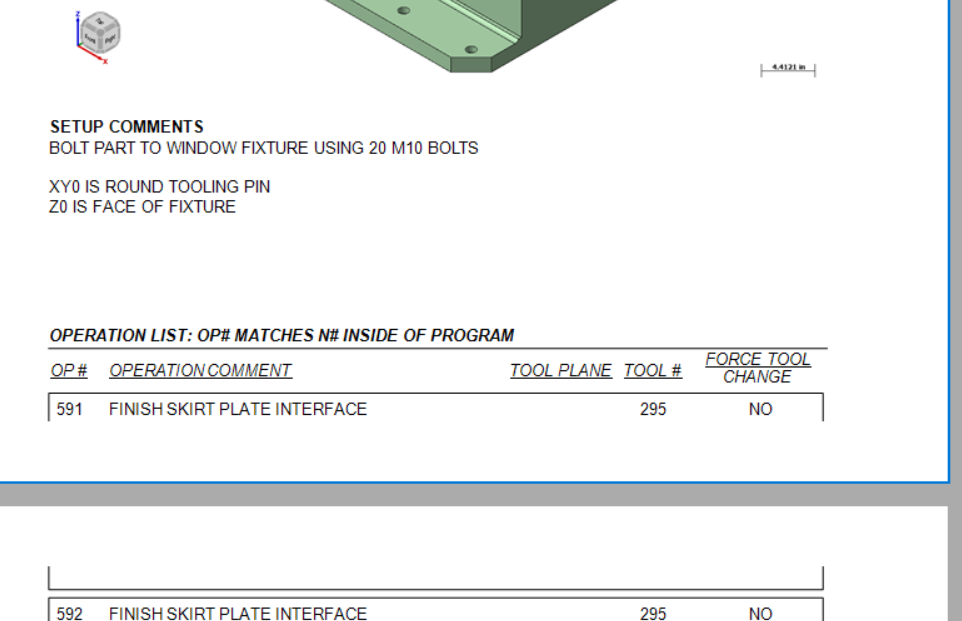
Setup Sheet, need information to start on next page.
cruzila replied to JB7280's topic in Industrial Forum
Just move the box down a little on that page. edit: it is a bit of a PITA -
Sorry if I used too many words Correct that Mastercam doesn't (to my knowledge) have a way to create an arc from two tangent lines and a single contact point. Yep, I was going off of the original problem (at the top of this reply). What I'm saying is your second reply where you added the video gave the crucial constraint, at that point you've completed the puzzle. I'm guessing you'll be able to chook it fairly easily now that you've figured out how to do it. It probably hasn't come up enough for someone at CNC to take a look at it, because how often is this scenario encountered?
-
Thanks for the reply! Wanna make sure I understand this statement correctly. You're saying the original question does not have enough information to solve. This is because to create an arc tangent to a line, you must specify the tangent point. The tangent point cannot be derived for the bottom line without the radius, and the radius cannot be derived from the given info (a line and a point on the line). But don't I disprove this in the video I posted? Like you said, I derived the radius from the given information. Mastercam should be able to do the same thing I did in the background.... right? I disagree with this statement. The reason I chose the centerpoint I did was because of the original question. I want an arc tangent to the endpoint of the angled line. Only one arc exists that has this characteristic and is also tangent to the bottom line. It's entirely possible I'm misunderstanding something here, so please correct me if I am. With that said, I think we all agree Mastercam is not capable of solving the original question "easily". After thinking about Aarons response and writing this reply, I realize I have the capability to attempt to write a chook to solve this issue. I should have time tomorrow night to dig into this. Maybe I'll be another victim of Aaron's signature (love that signature BTW), maybe I'll make something that works. Either way I'll be back with an update. Another huge thanks for all the replies. Seems like it's been mostly machine-control or mill-turn related questions on eMC recently, was nice to get a CAD discussion going.
-
I'd suggest the opposite > try adding all three values (XY & Z) on the G43.4 line. As an alternative, I would suggest having the Post modified to include a G43 Hxx Zxx line, inside the G68.2 call, to pre-position the Tool Tip, to the same position as where the start of the G43.4 toolpath move is. If you do this, be sure #5006.6 is set to prevent "motion on G49", and also that "G49 comes just before "G69", then you can invoke TCP. G54 G17 G90 G00 B-90. C-180. G68.2 X0. Y0. Z0. I90. J90. K0. G53.1 X-1.8735 Y3. S1000 M03 G43 H10 Z6.7 G49 G69 G05 P10000 G43.4 H10 X6.7 Y-1.8735 Z3. Z-.99445 X6.1 G01 X5.7 F25.
-
Occasionally I'm getting Z+ overtravel alarms when activating TCP (G43.4) on a Yasda YBMVi40 table-table 5 axis. The post is pre positioning using tilted work plane (G68.2) and then turning it off (G69) and activating G43.4 which normally works well. On large parts when my Z0 is set near the upper limits of my z travel I sometimes get overtravel alarms. When it reads the G43.4 line the machine is still treating the Z value as if the part wasn't tilting even though it is. In the couple of experiments I've done it seems like simply eliminating the Z value from the G43.4 line will solve the problem. Before I request a post edit I want to get some advice on whether this is a good idea. Is anyone using G43.4 without a Z value on the same line? Does anyone know of a reason why I shouldn't do this? I have workarounds to the problem but if this works I could quit fighting this issue. Sample code that is giving me a Z+ overtravel alarm. It works correctly after removing the Z value. G54 G17 G90 G00 B-90. C-180. G68.2 X0. Y0. Z0. I90. J90. K0. G53.1 X-1.8735 Y3. S1000 M03 G69 G05 P10000 G43.4 H10 Z6.7 <----------------- Can I eliminate this Z value ?? X6.7 Y-1.8735 Z3. <----------------- X6.7 on this line is actually a Z move. Machine moves to correct Z value even without Z on line above. Z-.99445 X6.1 G01 X5.7 F25.
-
 For Work Offsets in general, my preference is to "assign them to my Plane". (Don't use "automatic numbering" > -1 setting!) By making some edits to the Post, it is certainly easy to ensure the Work Offset is posted, and having it posted out for before the Tool Change, and also at the Null Tool Change, is certainly easy to do. Sounds like you may have solved some of this already. If you look in my signature, I've got videos of a Post Processor class I taught up on my YouTube channel. See "MP 101". 28 videos all about Post Processor Development.
 -
I'd be happy to share a z2g file, but no one asked. I'll be sure to include one in the future, so thanks for pointing that out. I'm new to these forums and just as new to editing post processors so I'm still learning the ropes. I think I can consider this particular issue resolved, and with the guidance of some other threads, I was able to get a work offset to post with every operation. Thanks again to everyone!
-

Setup Sheet, need information to start on next page.
JB7280 replied to JB7280's topic in Industrial Forum
Looks like I got it. I had tried that, but it wasn't working, initially. Looks like I had to make the whole "grid" area bigger, THEN increase the vertical length of that text box. Thank you for the help. -
.thumb.jpg.e1ed32e8dc33a68b1f20806bb5d55e08.jpg)
Setup Sheet, need information to start on next page.
nperry replied to JB7280's topic in Industrial Forum
Got it. So it's been a while since I've messed with it in great depth, but your setup comments box, could you just make that vertically longer to force the beginning of your operation list to start on a new page? -
If your machine is less then 20yrs old it should have a PCMCIA slot. You just need to change the comm. port on the control to use it instead of RS-232. If they don't it's easy to get the cable and slot. You can either buy a new bezel for your screen that has a spot for the card slot or you can probably make a hole in your existing bezel. Change a couple parameters and you're good to go. I have 1 horizontal mill with only 64kb of storage so any HSM toolpath has to reside on the memory card. However, to edit any toolpath on the card requires putting it on a pc, so if you want to be able to change the feedrate or maybe tool diameter offset if there's a CDC pass on the card you can substitute the F or D value with a variable#. I.E. if you program for F40, change it so it's F#500 (assuming you have extended variables, if not you can use #100-#150) then in your main program that's in the control you just need to insert #500=40. on the line before the M198. It's great for proving out 1st time run jobs to give the operator a way to edit the prg w/o dragging me to the floor for a simple edit like that.
-
Setup Sheet, need information to start on next page.
JB7280 replied to JB7280's topic in Industrial Forum
Thanks for the suggestion. That was already set to True, and unfortunately, didn't seem to have any effect one way or the other. -
A bit of a shortcut in your method is that you can skip the "extend the two lines to their intersection point" when you create the circle. Just hit "i" key or AutoCursor > Intersection and choose the two lines, it'll snap to the intersection. ----------- You need 2 pieces of information to create a tangent arc. If you have those two pieces of information, you can calculate the missing 3rd, right? There's a critical piece of missing information to solving this, which is either the tangent point (on the bottom line) or the radius. Without specifying those two, there's an effectively infinite amount of possible answers. When you extend the bisecting angle lines, you're creating the restriction on the radius (1.50881301") so there's only one solution that fits the end point of the slanted line and the center point (Radius), which means you'll get a tangent point on the lower line at X0.57622467". Unfortunately, unless you have a specific reason for choosing the centerpoint you did (i.e., it's called out by the print to find the bisecting angle between these two features and create the radius centered off of that?) it's just really a random point in space that confirmation bias makes look more likely to be correct Note that Tom found the solution in solid works effectively the same way, using Constraints instead of the geometry.. If you use Mastercam's Arc Tangent > Arc One Point, you're now constraining two items: The end of the angled line and whatever tangent position is closest to that line. Mastercam will make an arc fitting with whatever radius you type into the panel. You can make a Arc Tangent > Arc Two Entities, which will do exactly what fillet would do, (in the background) it'll extend the angled line to the intersection and fit an arc of 1" (or whatever you specify). ----------- Basically, you're not asking the right question. For two lines of N angle, you can ask: What radius fits between these lines? Any of them, pretty much. What radius is a fillet? How many windows are in a house? If I give you a point and a line, what radius fits between those two? Any of 'em > the distance between the closest point to line. See above. If I give you a radius, where does that fit from this point to a tangent point on this line? THERE YOU GO! That's the right one ----------- I can't imagine that any CAD/CAM system can give you what you're asking for, as you're not giving complete information.
-
All of the memory cards we use are 512MB or more. Most are over 4GB and we had any problems in the 10+ years we've been using cards this big Our oldest control in an 16i control from early 2000's and no problems there. Just have to watch the formatting. We have 2 machines that have memory cards that pretty much live connected to the controls.
-

Create Entities Groups C#
byte replied to eltklas's topic in Mastercam C-Hook, NET-Hook and VBScript Development
sure if you want to store multiple types in List<> the best way is to store the entity ids as long (or int for .NET ) to get the id you call GetEntityID(), then retrieve it using the Mastercam.Support.SearchManager function for retrieving the entity by id -
Setup Sheet, need information to start on next page.
nperry replied to JB7280's topic in Industrial Forum
JB - I know I struggled with this in the past and if I remember correctly it had something to do with the boxes in the lower section of the docked panel on the right. In the graphical section of active reports designer if you click the word "detail" it'll highlight that bar blue, then look at the menu to the bottom right. I could swear it was something in "behavior". Maybe try fiddling with the option "Keep Together". -
 Louis-André Abel joined the community
 -
Does anyone know how I can get the Operation section to start on the next page? I tried adding a PageBreak in between Setup Comments, and Operations, but when I do that, it wants to output a whole blank page.
-
 Ben Hersh joined the community
 -
 BradleyC joined the community
 -
Mastercam does not have the ability to make these constraints in this manner You learn something new every day!!!!
-
Any way to insert formulas into Active Reports setup sheets?
nperry replied to nholcom's topic in Industrial Forum
Went to add an edit and couldn't, but this should've gone with above post. So, OP, when you get blank pages like that it's typically because you aren't following the correct structure. It's difficult for me to make sense of the structure you have in place right now. My main sheet is (FILE), which calls (MILL-FILE), which calls (MILL-TOOLS), which calls (MILL-TOOL). Assuming you have (FILE) shown, you're then calling (FILE) and (MILL FILE) in the same report. Then one each of those calling (OPERATION) and (MILL TOOLS). I don't think that structure is agreeable. I think you need to be (FILE) - (MILL-FILE) and have that calling both (OPERATION) and (MILL TOOLS).- 12 replies
-
- 2
-

-
- activereports
- active
- (and 4 more)
-
We can't use "Fillet" because we don't know the radius.