Jake L
-
Posts
335 -
Joined
-
Last visited
-
Days Won
8
Content Type
Profiles
Forums
Downloads
Store
eMastercam Wiki
Blogs
Gallery
Events
Everything posted by Jake L
-
Agreed, this would be a good feature in optirough. There's cases where retracting would be faster, but there's definitely cases where "staying down" would be faster.
-
If it were me I'd post a file to prove my legitimacy.....
-
Not sure about your question, but I believe I read somewhere that "automatically determine Z depth" will be defaulted to off in MC25
-
I'm a firm believer that you can output any tool motion from Mastercam. That said, sometimes if you want something very specific it could take a while to set up. The motion could be achieved using a 2d dynamic path up to the fillet then contour paths to walk up the fillet. You'd need all the linking parameter values set to 0. This way the tool only ever retracts as high as the next toolpath. May need to play with the lead in/out's to not gouge the part. Might be easier to use optirough then convert the tool motion to wire. Modify the wire and use a 3D contour path with no cutter comp. Neither of these are "easy" or "good" options, but you can get Mastercam to output that motion.
-
myMastercam.com > Communities > Third Party Developers > whichever topic you want to view You'll need to email [email protected] to get access to the Third Party Developers page Your link brings me to the myMastercam login page, even if I'm already logged in. Then it puts me on the homepage after logging in
-
Wait actually??? Seems like a dirtbag with too much time on his hands. I tried as well with no good results. Area Rough allows use of extra keep tool down options but then you lose step up. Optirough has stepup but you lose the keep tool down options.
-
Typically if I need to trim a solid to more than one surface, I'll do each surface one at a time using "trim to surface/sheet". I do not know of a way to trim to more than one surface at the same time.
-
Speak of the devil, that's what we're upgrading from
-

Posting 2 different B0 machining operations, no rotation commands.
Jake L replied to JB7280's topic in Industrial Forum
I've run into the same thing before. My workaround was using a manual entry with: rotary unlock, new offset B0, rotary lock. I'm sure you could make this happen automatically with the post but I haven't had the time to play with it. You could probably accomplish the same thing with a force tool change, tho this would probably add unnecessary motion. I'm also interested if there is a better way. -
I just heard we went with Cimco. Sounds like after including all the necessary add-ons in a new quote, Predator was a couple thousand more expensive than Cimco. The plan last summer was to have the new DNC setup and running 2024 Q1... The current plan is to start installing 2024 Q2. Going off that trend, I'm crossing my fingers we'll have it up and running sometime before 2025. I'll try to come back and update, but I don't think I will be involved in the install.
-
What is the NCBase? Do we need it? I think in total we're around 50-60 machines I'm pretty close to giving up on fighting for Cimco. I talked to our maitanance guy and he asked why they wanted Predator instead of Cimco. He said it didn't make sense why they wouldn't go with Cimco because it's "industry standard". I talked to our floor manager and his response was "I never even heard of Predator before, why aren't we going with Cimco?" I told him I couldn't come up with any hard evidence of why to spend the extra money. He said without hard evidence management probably won't spend an extra dime. Which is a shame. My point is, it seems everyone here except the people with the money think we should be getting Cimco. //rant over
-
Taking a shot in the dark here, but it sounds like your post was designed with and option to have an M01 OR M00 at the end of a tool. If so, the misc value you're setting will only have an effect with force tool change on, or if the operation is the last operation for that tool. +1 to putting M00 in a manual entry
-
Show up and take a shot at one of the most knowledgeable guys on this forum... doesn't seem like the smartest move to me
-
chook operation simulation points
Jake L replied to michiAMT's topic in Mastercam C-Hook, NET-Hook and VBScript Development
There's probably an easier way to do this, but first thing that comes to mind is reading the NCI data to get x/y/z coordinates. Not sure the NCI stores tool orientation tho... https://my.mastercam.com/forums/topic/anyone-knows-c-hook-nci/ -
Getting correct offset output in Transform toolpath
Jake L replied to JB7280's topic in Industrial Forum
If you check the "include WCS" box, the B180 side should post out as B0 -
Getting correct offset output in Transform toolpath
Jake L replied to JB7280's topic in Industrial Forum
No worries, JP knows a lot more than I do anyways. Don't think I would've caught the "slight skew", but good to know in case I run into something similar. -
Getting correct offset output in Transform toolpath
Jake L replied to JB7280's topic in Industrial Forum
Hard to fully understand what you've currently got without a file. I understand what you're looking for but there are some holes: are op3 offset 10-14 5 separate parts all at B90? or are those 5 different angles on one part? Using a generic post or something custom? Got any options on the toolpaths misc. values page? What does the output for B270 OP3 look like with your settings above? Do they get assigned new work offsets? Or do the B90 OP3 offsets get copied for B270? One of these days someone is going to ask a transform question and I'm gonna take some time to do some research and make a long post explaining each option and common pitfalls. Unfortunately today is not that day, but some day. -
Pitch in your little gems that make mcam life easier
Jake L replied to jlw™'s topic in Industrial Forum
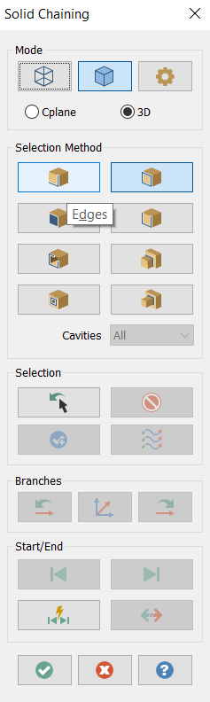
Can't believe I've never noticed this before. If you hover over a button in Mastercam, if there is a programmed hotkey for that button, the letter will be underlined. In the picture, if I want to switch to "edges" selection method, d is underlined so d is the hotkey.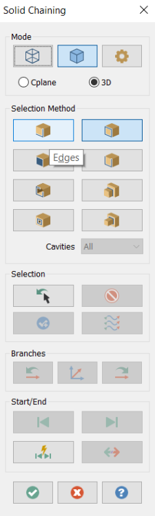
-
F1 and F2 are your friends for zoom in/out quickly
-
chook mcam file name
Jake L replied to michiAMT's topic in Mastercam C-Hook, NET-Hook and VBScript Development
I might need someone else to step in here. I thought this would work: CString filepath; SysFile f; filepath = f.GetFullName(); but I think I'm doing something wrong when declaring f because this is the value f gets set to: <Information not available, no symbols loaded for MCCoreBase.dll> -
chook mcam file name
Jake L replied to michiAMT's topic in Mastercam C-Hook, NET-Hook and VBScript Development
SysFile_CH.h https://my.mastercam.com/forums/topic/close-current-document/ -
A Nethook to Chook problem
Jake L replied to piaofcu's topic in Mastercam C-Hook, NET-Hook and VBScript Development
I think you need to use the TpOpList class -
A double angle cutter would be perfect for this https://www.harveytool.com/products/specialty-profiles/double-angle-shank-cutters But you asked about using the 1/4 ball endmill. If I open your op26 and select just the X+ hole instead of both for user defined edges, I get a good motion. For some reason it doesn't like the other hole. Maybe try recreating the geometry? It won't even do the X- hole if you select it by itself, kinda strange...
- 1 reply
-
- 2
-

-
Figured I should answer my own questions after a conversation with @GoetzInd 4. G54.4 is useful on a 4-axis machine because it eliminates the need to position your fixture perfectly to where it was programmed in the CAM software. 5. G68.2 and G54.4 are completely separate functions. 54.4 is work error comp. G68.2 is tilted workplane, used for setting the zero point of your program to something other than COR. This makes the numbers in the program "make sense" so it's much easier for the machinist to make adjustments at the machine. Both functions can be used independently, or in conjunction. One other major thing I learned is Tool Center Point (TCP) which is G43.4. This causes the x/y/z numbers in the program to be at the tip of the tool. This is used when rotating one or more axis while in the cut. It's another function that makes the code easier to read for the machinist. Thanks again for reaching out and sharing so much information Mike!
-
You mean like converting the scientific notation to standard form? https://www.calculatorsoup.com/calculators/math/scientific-notation-converter.php