Aaron Eberhard
-
Posts
1,413 -
Joined
-
Last visited
-
Days Won
103
Content Type
Profiles
Forums
Downloads
Store
eMastercam Wiki
Blogs
Gallery
Events
Everything posted by Aaron Eberhard
-

x7 facing tool path verification error
Aaron Eberhard replied to ken wong's topic in Industrial Forum
I thought I already told you that was in the works, Keith -
x7 facing tool path verification error
Aaron Eberhard replied to ken wong's topic in Industrial Forum
As of this moment, there's no way to force it to go into 5 axis mode from the XML or config. Look for that to be addressed in the future. I'm not sure if that's slated for an SP, or if it'll wait for the MU.. -
My advice on the advanced multiaxis: Understand that Morph Between 2 Curves and Morph Between 2 surfaces will do 90% of everything you need. 2 curves is the multiaxis equivalent of blend, surfaces is the same, except "3d" (if that makes sense). The most important thing to start with is getting the correct pattern you're trying to cut. Like CJep says above, When I started out, I often just created one of those toolpaths, choose my tool, the curves, the surfaces and then hit "okay." Only after I have something down will I start going to change things. I would tweak the toolpath settings until I had the right pattern on the part, and then I would start playing with the collision settings. The next is how you want the tool to move (Tool axis control). This is really challenging to think about "Okay, how do I want the tool to tip through here." Collision Control are the "tricky" part of multiaxis, and you really have to think long and hard about what exactly you expect the toolpath to do. For example, "Just move away" doesn't help. Do you want it to move away on the surface normal, the tool vector, just "up" in the Z? It's a lot harder than you think The thing about multiaxis is a lot of things you take for granted (X travel, Y travel, ESPECIALLY Z travel) are no longer "fixed" so now you have to think about how to control it. When you were in 3 or 4 axis mode, you can always guarantee your tool is vertical, so if you could see it, you could cut it.. Good luck, it's a lot of fun!
-
Cool, it's a great cure for insomnia, eh?
-
You have to convert the file to the new tooldb extension (instead of a tools-X) file. You can do that with the update folders utility, or in a toolpath in Mastercam, open that database and the save it as a .tooldb.
-
Okay, glad you got it sorted! It's the field that tells you what size tools the cut parameter applies to.. i.e.: This cut parameter works with anything from a .375" to a .75" tool. Or, if they're both the same, you're saying, "This only works with .5" tools" or whatever.
-
Yeah, it's not quite as modular as we'd like yet... But we'll start dropping things out of the updates as we can confirm it won't break anything. You'll see the weight falling off in the future
-
We're hoping that the public shaming that would happen if you started breaking tools due to the recommended feeds and speeds will keep people in line Seriously, there is some range (min/max) things that aren't exposed, but we're collecting data on. The hope is to eventually have a nice adjustment mechanism like a slide-bar or some equivalent to allow you to adjust within the range specified by the manufacturer. So if you find their recommendations are on the high side, you can just slide it down a bit to the level that works with your material and machine.. Think of the ISCAR HEM calculator/HEM Factor thing.
-
I have no insight nor control in that sphere, but I'm going to guess not... One of the big reasons we can release HLE is the lock down that happens to the data inside.. It's really not worth the effort to try to lock down all of the ways you can get data out of Mach Sim (nor all the work that could mess up everything it "touches", so I think the easier solution was to simply limit the data you could put into it..
-
I can tell you we're working with the manufacturers now, I'm not sure when we will be ready to start releasing the libraries, but it is under live development. Gms1 - They're a type of collet, kinda like ERxx collets. You'll find them more in Asia or Europe..
-
At least you're on the right path! I think it has to do with the fact that you can export things through the Machine Simulation area, so I'm sure that's why it's locked out with the HLE...
-
You're welcome, I'm glad it helped! I'm not sure what issue you're having with the filter, can you describe it a bit better, please? If I build two assemblies, one an endmill, one a ball mill, in Mastercam, I can use the normal filters even when I have it checked to assemblies?
-
Chad, If you get it all the time, I'm sure QC would love to be in touch with you, since you can repeat it. Email [email protected] or [email protected] to get started. Thanks!
-
Hey guys - I was talking to the tech services people about this, and they pointed out that Solids don't work in HLE with respect to MachSim.. Try converting the solids to surfaces (Create > Surface > Surface from Solids), and use those for your fixture & such. Most likely, the buttons are greyed out, because "there's nothing there" for it to display. Hope this helps!
-
Jyrgus - Can you reproduce the steps that led up to it? if so, write down (or better yet, record like you did there) those steps, and get that into [email protected]. From the video, though, it looked like it was already processing that multithreaded toolpath, and was waiting to put it back into the ops manager but something was preventing it. I know this thread is old, but I tried Hitachi's steps above, and didn't have any issues on my X7 SP1.
-
I assume you're meaning save an STL from backplot/verify? You do have both options, you can still save out of verify. Comparing stock model to traditional verify, and they both did the same thing: Simulate physically pulling the tool to remove material, and what you're left with is a model where every tool contact point is represented by a triangular mesh (STL). Both took about the same time on older, single core/non multi-threaded machines. Fast forward a few years to the modern era, and although the output is the same, stock model is multi-threaded and 64 bit (capable of using more than 4gb of ram), verify wasn't. In most situations, you don't need to see every single triangle of the mesh of your cut, in fact, it just slows you down. If you ever tried to rotate a huge assembly/complicated cut in the old verify, you've seen it, laggy redraws, sometimes graphical glitches, etc. Most of the time, people use verify to just see where the tool is going, what material is removed, etc, so you don't need to have every single triangle of a corner displayed, and you don't need to lose the time simulating every little facet. The idea was to redo verify so it was actually useful for larger/more complicated cuts, and drop some of the finite resolution so computers can handle it and it runs well, especially since we already had a utility that was better & faster for creating accurate STL than old verify ever was (stock model). Of course, if there's one area you need to see better, there is "Accurate Zoom", which will give you approximately the same quality as old Verify for the area of the screen you're zoomed in on. One thing that helps people aclimate to the new Verify is to turn off Color Loop. Color Loop shows each toolpath's material removal as a different color. In an area with a lot of overlap, this can create a colorful mosiac... Old verify just showed everything as yellow, so sometimes it's a bit less disconcerting to see it the same way. With either option now (stock model or verify), you can have it processing in the background while you continue to work. Before, you were stuck. Hit verify, crank up the quality and wait.
-
You can also offset surfaces negatively, i.e. : -.125, or use "single flip" if just one surface offset the wrong way..
-
klgroebner - That looks like a windows/other program issue for the first one, and I'm not sure about the second.. I'd send those in to [email protected], and they can get the appropriate information from you or get it in front of the right people..
-
Michael - If you look close at the one side, you have a chamfer on the edge (I highlighted it in green in my attached picture).. If you remove that first, you can successfully remove those grooves as well. In the future, on a shape like this, I'd remove all fillets, first (Solids > Remove Solid Fillets, then set it to "all matching radiuses"), as it'll make the selection faster.. Cheers, Aaron

-
X7 verify How to select what to keep after verify
Aaron Eberhard replied to Cannon's topic in Industrial Forum
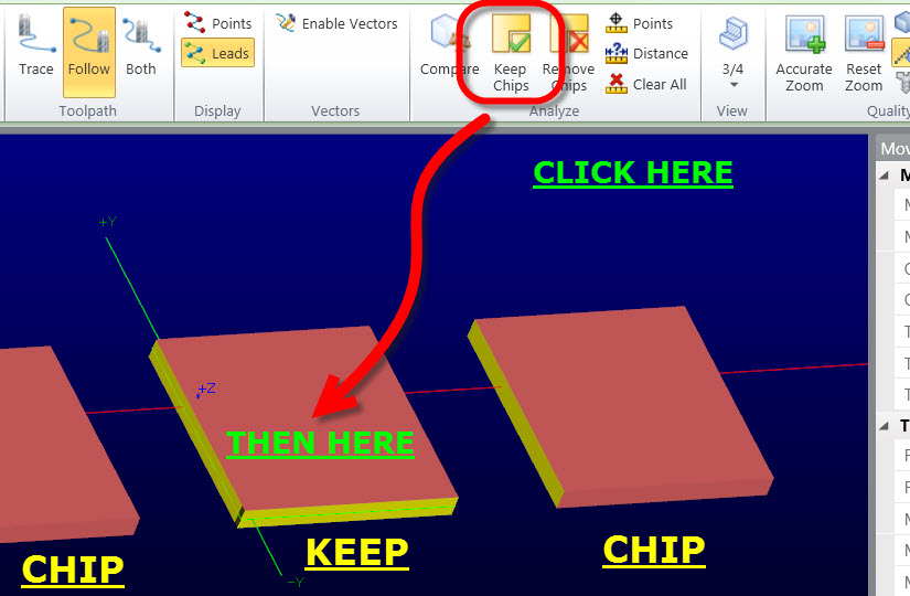
Cannon - What you're looking for is the Keep or Remove chips feature: In this example, the middle is the "keeper" and the two on the outside is extraneous, if you click on "Keep" and then click on the keeper, it'll get rid of the two outside ones. If you click on "remove" and then click on any piece, it'll remove that one piece. SKIR68 - If you look to the right of the Keep/Remove chips button, there's a sectional view button that gives you different options.
-
Keith - that'll be cool, I had a great time hanging out with you, Shawn and Dan. Sure, the user group is our attempt to foster a Mcam user group in our area, so geeks like us have a place to go and hang out and talk about tech & such once a month or two. Since it's our home territory, we'll have inside scoops for members. It'll be interesting to see where it goes, but we think it could be a lot of fun, and very helpful to everyone involved.
-
Yep, it did crash on me during the webinar... I do have all kinds of odd things using 3d programs while I'm doing a goto(meeting|webinar), though... I think it has something to do with the JVM interpretation of the desktop area or something. I hadn't had a tool manager crash since beta 2 before that (of course, it has to happen live!) klgroebner - You can't assign cut information to a material type, only as a cut parameter. On the cut parameters, there's only one feed & speed per parameter, as the point of them is to have a "plug and play" situation where you know choosing the right parameter will give you the proper (and eventually proven!) feed & speed. Mike - Yeah, it definitely takes a few goes to get your head around what it's asking and how to ask for it. It's the downside of having crazy amounts of power behind it, you have to be quite studious with your library descriptions & organization. Michael - What kinds of things have you been seeing? Have you been in touch with QC at all?
-
MCX7 - .HOLDERS to .TOOLDB Question
Aaron Eberhard replied to Brian B 74's topic in Industrial Forum
Brian - Update folder has worked for me, but here's my second try: in X7, open any old toolpath, and under the "holder" tab, choose "open library" and open up your X6 library, then just hit "save library" and save it as a new .tooldb. Note: You may have to choose .holders as the file type when opening and .tooldb when saving. Hope this helps! -
Would you mind shooting a copy of your X6 library over to tech support here, I'm sure the tool guys would love to see that. Not that I would want to see it happen to anyone, but it's really easy to do a mass edit on them.. I figured a picture is worth 1000 words, so a video would be worth a lot more You should be able to see it here, youtube says it's processing and will be availible in a few minutes: http://www.youtube.com/watch?v=oKNf0kG6mo0&feature=youtu.be
-
Hey guys, I finally got back into the office and got the webinars available for download off of the Mastercam site. From Mastercam.com > Multimedia > Product Demos.