Aaron Eberhard
-
Posts
1,412 -
Joined
-
Last visited
-
Days Won
103
Content Type
Profiles
Forums
Downloads
Store
eMastercam Wiki
Blogs
Gallery
Events
Everything posted by Aaron Eberhard
-
Ah, now I see.. When you click, you're "Grabbing" the geometry you want to move. If you hit the green check before you release it, you haven't completed the command, so it's the same as hitting esc or some other cancel.. What you want to do is click to "release" the geometry you've grabbed, and then you can hit the green checkbox (or just double click to accept it). Edit: You're welcome, I was just in the right place at the right time
-
I don't understand??
-
Yeah, that's a hard trap to avoid I can say, once you get used to Xform Dynamic, it's tough to go back.. Having basically 4 tools wrapped up in one is awesome.
-
Or just use Xform Dynamic, which operates in INC from where ever you choose your base point as.
-
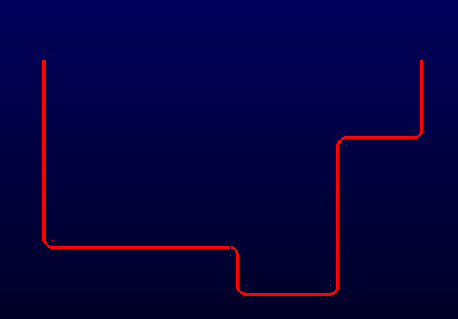
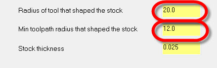
Glad you like it, Kevin! You should use both options... The idea is that this toolpath doesn't really "look" at stock remaining from another toolpath (like a rest machining/optirest toolpath would), so you have to tell it what you did previously. Technically, you only need to define the stock thickness remaining, and it'll calculate a toolpath based on that (as if the chain is "offset"), but of course you won't know if there's one area with more stock remaining from roughing with a big tool, it would just treat the whole thing you're cutting as a set thickness. So if you had a shape like this one: I have fillet radius of 5mm set in each corner, and I'm finishing with a 5mm mill. If I had roughed that out, I would use a tool with a diameter of, say, 20mm, and I may tell the the roughing toolpath to have a minimum arc radius of 12mm. I need to tell Dynamic Contour that so it can properly calculate where material is left and how to attack it:


-
Yep, it's built into the Curve 5 Axis and Swarf 5 Axis for X7. You have your choice between doing a linear move (which will give you sharp corners) or high speed which will give you a nice smooth wave.. Look for it in the collision control section.
-
MWR15 - I'm glad to hear your problem has been addressed for the latest release.
-
I would do that with two simple "flat boundary surfaces" If you can get the solids, in X7 you can use "Modify Solid Body" to create a plug that would fill it nicely...
-
MWR - Have you tried it in X7, or followed up with the bug # through your reseller or Tom? If that bug was discovered after X6 was past it's last update release (MU2), all fixes go to the next version, so it would be logical that the solution may be to update to X7 if the bug was fixed for that...
-
If you're not running a nethasp, though, it's how ever many sims (the USB key you have to plug in to use the software) you have...
-
Just a bit of further elaboration: If you find yourself creating a lot of lofted or ruled surfaces or making toolpaths that use Sync like Swarf you can set this ahead of time and save it to the configuration by going to Settings > Configuration > Chaining > Sync Mode. I've found that "by entity" is the most reliable and easiest to understand sync mode, because you simply make sure each chain has the same break points, and it will always sync predictably. Some of the other ones can get a bit tricky..
-
Any impeller with a closed shroud is actually a Port G - Let me know what questions you have on it, I'd be happy to run one of your parts through a sample toolpath and talk about the best way to attack it..
-
Sounds like you're on the right path! Just a quick question: Do you have a DECENT SSD running your rig? There's a lot of load/save time to be had with that over the old spinners
-
Just for a little history on this, the reason for the option to safely remove it is from the windows 2000 SP2(ish) era, when USB 1.0 & associated media was really slow. In order to make things "seem" peppier, Microsoft made the call to use what's called "Delayed Write" (google it as Windows Delayed Write or equivalent). The idea was that if you told it you were going to copy a file, it would put it in a cache and start writing it was soon as windows detected nothing else was going on. Of course, most people ended up writing a file and immediately tried to pull out the unit, but the file hadn't been copied yet. They added "Safely Remove Hardware" as a command to finish writing the contents. This is what the performance mode referenced on the first page will still do, but of course modern devices & USB are fast enough it's not worth the risk to your data. I believe this was phased out in windows XP SP2. Now you should be safe if you just wait for the light to stop flashing (indicating it's done reading or writing data).
-
It may be better for you that maintenance expired. "A luxury, once sampled, becomes necessity" it is said... And it would quickly become necessity for me if I were working with stuff like that.
-
kdgrills - I can't believe you're working on 1Gb+ files without using the latest version... Ouch! The (computer) hardware usage is way better in X6, and better yet on X7. Take it for a test drive, I think you'll like it.
-
Bill - Right on the speed control & slider bar at the top of the graphics window, between the Fast Forward to End button and the speed slider..
-
That's really odd, I haven't seen any issues on my system using it.. Definitely send a copy of an example to [email protected] about that..
-
GMS - Send it over to [email protected], please. They're monitoring it specifically for the X7 line. Thanks for all the help!
-
There's not a results difference between the 3 axis and 5 axis backplot and verify engines, just the 3 axis engine is a lot quicker (because there's less to computer), so that's the preferred default. There's no harm in playing with the 5 axis backplot other than decreased performance. GMS - Would you send a sample over to the x7 team to make sure they've seen what you're experiencing with your backplot?
-
GMS - Check out your Backplot/Verify Options... You can load different STLs or Stock Models from there. After you load a new model, just choose which toolpath you want to see and hit backplot or verify again, and it'll update. It's a little disorienting because the models aren't managed inside of verify like they used to be, but once you know about it, it's quite nice..


-

MasterCam 7 and the moldbase c-hook
Aaron Eberhard replied to chris graf's topic in Industrial Forum
Chris - This in no way mitigates your pain from having to redo work, but if you do go forward using FBM to do it, look into using Change Recognition to if the parts are similar, but just different dimensions and minor features. Look it up in the help system for an example, it's pretty smooth for doing repetitive parts. And I can't be the only one who sees a car for sale, says "Oh hey, that's from 2000. It's practically new!" before realizing it's 13 years old, right? -
MasterCam 7 and the moldbase c-hook
Aaron Eberhard replied to chris graf's topic in Industrial Forum
Chris - I'm not familiar with MoldBase, but your example sounds like something that could be done with FBM? -
SpecProgrammer - Unfortunately, no. You can't have individual levels have graphic attributes, they're across the board (wireframe/shaded/translucent).
-
Good to know. Sometime when I'm stuck on the couch I'll whip something up