daryl_y
-
Posts
51 -
Joined
-
Last visited
Content Type
Profiles
Forums
Downloads
Store
eMastercam Wiki
Blogs
Gallery
Events
Everything posted by daryl_y
-
Tool life of over 120 minutes, and this has been observed on multiple different parts. Our spindles are either 50 taper or HSK 100 and we use heat shrink holders with thru-tool coolant. The speed and feed that I stated we use is also the speed and feed you should get if you enter the parameters into HSM advisor. I think HSM advisor feeds and speeds are right on for titanium.
-
I'll play For a while my go to cut strategy in Titanium with a .750 5FL Helical brand end mill (1.62 LOC, .12R) has been: 8% Step over, up to full step down, 525 SFM, .0045 chip load ( 2676 RPM, 60 IPM).
-
We have quite a few HSK-63A spindles over here. We have bought a few long reach ER16 and ER32 collet chucks from Lyndex Nikken but usually long reach tool holders outside of heat shrink holders are hard to find in HSK. They do make "HSK Adapters" that stack up with your existing tool holder to give you a longer gage length but they will not be much help if you need to get a small holder in a tight place.
-
dynamic toolpaths using zig zag cutting method
daryl_y replied to wholaday3's topic in Industrial Forum
When using tool path like 2D High Speed Blend I have used zig-zaged in aluminum and have not had any issues. I have always used climb cutting with the Dynamic tools paths even if these are set to zig-zag they still make a pretty big lead-off and lead-in to you part and seems like there would be a minimal (if any) real time savings. I doubt you will have any issues aluminum or any other soft material doing this. -
I would not use a large face mill. The Aluminum face mills we have here (Kennametal Fix Perfect) cut too free and do not do a very good job of getting a thin part flat. I would use a smaller 90 deg inserted end mill 2.00 Dia or less with a .12R or so on the inserts, something that might put a little stress back in the part. I have had better luck getting parts flat when you face from the inside out like a pocket.
-
At the upper end of your price range 400K you are also in the ballpark for new machines from companies like OKK, Okuma and Mazak. A notch down from Makino perhaps but still good machines. We have 4 Mazak 6800's (50 taper) and 2 Mazak 4000's (40 taper) Horizontal machines at my workplace and they have all been very capable and reliable. A Mazak 6800 fits your description of what you need . While the 4000's are probably to small. One of these would be a good find new or used.
-
There is a product from Mazak the we use at our company called Matrix Cam. It allows you to write programs in Mazatrol and simulate programs (Mazatrol or .EIA) on a PC using the same graphics and simulation that you have at the machine. It is ok for verifying simple stuff but for a complicated 5axis project it is so slow that it is not really usable. When we got our first 5axis machine, a Hermle C40 back in 2006 it came with a seat of Camplete. It was nice that a post was intergrated into it that is easy to edit and set up . Even someone with no 5axis experience (me at the time) was up and running rather quickly. But it does not simulate G-code, you export your NCI file to it, piece your program together, set up your simulation and post out your G-code. This is a huge hassle for not really new programs but for editing and updating old ones because you can not verify what you cut and pasted into the code or verify what came back from the machines. We stared using Vericut about 5 years ago and never looked back. With the Mastercam interface (which is a add-on) simulating programs are much faster than Camplete. The down side to Vericut of course that it costs a lot more, you need post, and will probably need to get some training from you Vericut reseller.
-
We have had the same issue on our boxes here. I do not think you can delete any of the columns in Tool manager, If you do not want to view some of the columns grab the column and slide it closed but stop just short of closing in completely. If you close the column completely your settings will not stick.
-
I am using X9 and I currently keep separate tool libraries for tools and tool holders in Mastercam. I find this to be an easier way to do things since it keeps my libraries of "tools" clean since I can keep only hand full of .750 endmills for example in my library and put them in whatever holder I need too. Our shop also has several different kinds of spindles (HSK, 40 and 50 taper) so I have multiple holder libraries in Ops manager if I selected a tool that I have already placed in a holder and select "save tool" it will save that tool as an assembly which is not what I want, I only want the tool saved. Is there a way to save only the tool in X9? Or to break apart the assembly after it has already been made?
-
Issue importing solids into Mastercam (everthing on a separate level)
daryl_y replied to daryl_y's topic in Industrial Forum
Thanks, Got it figured out. Works exactly as John McCord says: -
So, I have a Mastercam file of a Kurt vise that is made up of 20-30 separate solids with everything on a single level. I export this file as a STEP file and I open it in my CAD program (Keycreator) everything is correct (level is named correctly and the entities are on the level that a specified in Mastercam) but if I import the same STEP file I just exported with Mastercam it comes in to Mastercam with each solid on its own level. Is there a setting in Mastercam to fix this? It sure would be nice if everything would import with the same levels and level names as the CAD file. I Really do not want to have separate tooling models/ files for Mastercam and CAD. I have tried this with multiple file types (STEP,SAT,IGES) and 2 different CAD programs (Keycreator and CATIA) and have gotten the same result.
-
Another way is to use stock model select the "solid" option and window around all the solids that you want as your stock, then select that stock model when you verify. Boolean add is an option is the solids drop down and is a way to combine multiple solids into one. You pick one solid as your target and the others to add to it.
-
When you slide the columns around do not slide them so far that you completely eliminate the unwanted column. If you leave a little space your changes will stick. For me the last few versions of Mastercam have acted this way.
-
From a job I just did a couple of weeks ago that was 6061 Alum. .031 2FL carbide ballnose 13300 RPM, 20 IPM, .003 Stepover, the tool was just re-machining a couple of radii that was left behind by a larger tool. The job was ran on a small 40 taper Mazak horizontal with a 14K spindle.
-
When I program feed mills I usually use the Opticore toolpath, I think it makes a smoother tool path that is easier on the tool. Also, it is usually cuts the part a couple of minutes faster than using surface rough pocket or core roughing. Looking at the picture of your part, the outside profile the part looks pretty shallow. My 2 cents is that you would be better off cutting that feature of the part with a end mill using a full depth of cut and small step over using a tool path like Dynamic 2D or Opticore. Depending on the shape of your part feed mills can be great for roughing some parts close to net shape. But, I think endmills can cut shallow 2D shapes just as fast and do not have to watched as close as by the machinist or operator.
-
Sorry I had to go off the grid for a couple of days I tried a few different things but nothing that was satifsfactory besides simply drawing the tool. My reseller (QTE) was at my work and had a look at it, I will be sending them files.
-
Did you know Mastercam has "hidden" 5-axis toolpaths?
daryl_y replied to Colin Gilchrist's topic in Industrial Forum
Hmmm. I have seen the triangular mesh toolpath but never thought to give it a try. The Module works toolpaths, parallel to muliple curves and morph between 2 curves I like and use a lot, These are also not just for 5 axis work and can be used in place of other surface toolpaths like parallel, flowline and blend. Once you get past the initail settings (Mastercam really needs to figure out how to implement defualts on these) they are easy to use and give you a lot more control over the tool path. -
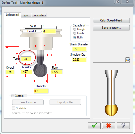
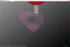
I am using X7 MU2 and have been for the last 6 months or so. I do not program with undercut tools very often but I have not had one display or verify correctly in X7 with out having to draw the tool. Attached is a screen shot of a undercut tool that verifies and backplots correctly in X6 and one of the same tool in X7. The X7 tool would not even backplot until I changed the taper length from .12 to .25 and still displays horribly wrong in verify. Please see the attached pictures, Again, I am able to work around this by drawing the profile of the tool but this seems like a hassle since this worked correctly in previous versions. Thanks in advance for your help


-
Thank you all for your help. Sorry for the slow response I did not get any chance to "play" on the forums yesterday Aaron, I changed my precision index to 5 and precision factor to 1.25 and it made big difference speed wise on this part. I did not start using X7 until after MU1 came out, my first couple of parts I did with X7MU1(which were very large) I was not happy with the quality of the verify. I did some research on the forums here and started playing with the P-factor and P-index settings I wound up with a P-factor of 2 and my P index of 6 and was happy with the results for a few weeks. I did not have any verify issues until I started on this part which was much smaller that the parts I was programming before. Like Camman says I made need to have mulitple 1 simulator default files for different size parts.
-
My computer is pretty high end: Windows 7 64 bit Intel Core I7-3970X @ 3.50 GHZ 32 GB Ram Nivida Quadro K5000 4GB video card.
-
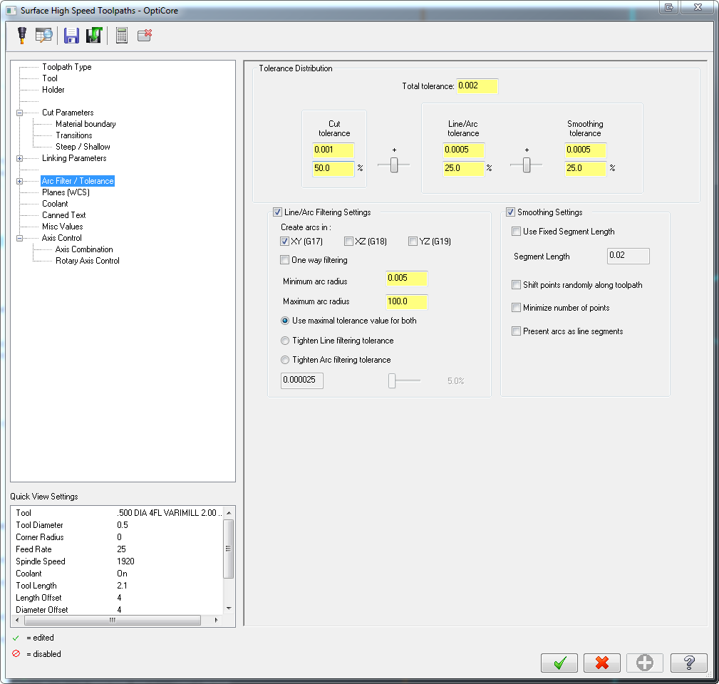
I have been using X7 MU1 for a couple of months and just updated to MU2 yesterday. So far with X7 I have been happy (more or less) with the new verify. I just finished up a family of parts that were rather large (40.00 x 30.00 x 5.00 ) and complicated 3 axis parts and was very happy with the speed of the verify in X7. Then I come across this little (and simple) part that is 2.50 x 2.25 x 2.00 and the verify is slow as Christmas especially the Opticore tool paths at the start of the program. In my Mastercam simulator defautls file my precision factor is 2 and my precision index is 6 which in the past I have been happy with. I have attached the X7 file and a screen shot of my filter settings for my Opticore toolpaths. Please see if you can find out what is making verify run so slow. 10341.MCX-7
-
Sorry forgot to attach the picture.
-
You can do it all inside the dynamic milling path, use a circle smaller than you entry hole for a custom entry (circle will have to be broken into a couple of pieces to work) and use another circle smaller than your entry chain as an avoidance area. .
-
We just had a Mazak VTC 250 come into our shop from another building and it has the older Mazak Fusion 640 control. For years we have used a letter prefix in our program #'s to differentiate what machine it was programmed for, Example program # H1234 is for a Hass, program # V1234 is the same program except for a OKK etc. We have never had an issue with this on any of our other machines and we have many different ones, have Hass, OKK, Hermle, and several Mazaks with the newer Matrix control. It seems that the Mazak Fusion control will not read a program with a letter in front of it, it will read prog# 1234 but not X1234 for example, Has any one found away around this? We have been converting proven programs over to this machine and running them there and this issue is throwing a wrench into the works. Currently our programs are stored on the network and then moved to another folder on the network that the machine is set-up to read from. The only solution I have came up with so far is to have them rename the copy of the program in the machine folder using windows and then have the machine read it in. (For example change X1234 to 1234 and read it in) but this is relies on the operators not to screw anything up and the file will have to be renamed again (from 1234 to X1234 ) before saving it back to the server. Note when I say program numbers I am talking about what the program is actually named not the number at the top of file.
-
Thanks for the good advice guys. I am still having trouble with our Mazaks though. I have exported tool data as a text file (.DAD on Matrix and .M6V on Fusion controls) and compared them to the what the Zoller is posting out and honestly the formats look the same to me, but the machine will throw an error when trying to import the Zoller information. I can changed a couple of values in the machine and import the tool data that I just exported back to the machine so I know that Iam importing the data correctly. Obviously I am missing something, tomorrow I will be sending the files to Mazak to see if they can tell whats wrong with them.