Roger
-
Posts
502 -
Joined
-
Last visited
-
Days Won
1
Content Type
Profiles
Forums
Downloads
Store
eMastercam Wiki
Blogs
Gallery
Events
Everything posted by Roger
-
My corner rounding endmill looks good in backplot, but in verify it doesn't show correctly, or cut the radius correctly. Can someone take a look, give advice?? I'm using Mastercam 2019. corner rounding.mcam
-
Opinions please. We do mostly 2D work with some (2d Dynamic Mill paths) A few surface tool paths, now and then. Maybe in the future some 5 axis work..... Precision 5820 Intel Core i7-9800X 3.8GHz, 4.5 GHz Turbo, 8C 16.5MB Cache, HT, (165W, DDR4-2666 Non-ECC Windows 10 Pro 64 bit NVIDA Quadro P4000, 8GB, 4 DP (5820T) Precision 5820 Tower Core X 950W RTX Chassis 32GB 2x16GB DDR4 266MHz UDIMM Non-ECC Intel Dual Band Wireless AC 8265 (802.11ac) 2x2 + Bluetooth module 2.5" 512 GB SATA Class 20 Solid State Drive 2TB 7200RPM 3.5 SATA Hard Drive 8X DVD+/-RW Slimline 5.25" FlexBay No Optical
-
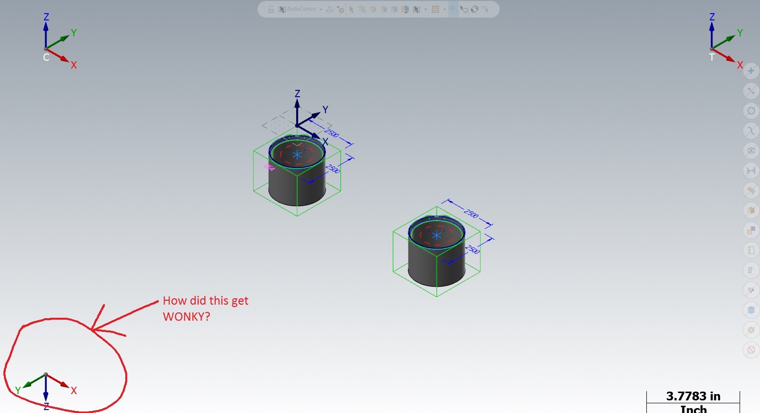
When I opened the file the WCS is not showing correctly. What happened? More important, is how do I get it back to normal?????????????????

-
I think he is asking about color in simulation, not verify..... I don't use simulation, so I can't give any answers...........
-
IT guy was in. Worked on it for 45 minutes. He couldn't fix it.............. Said Windows 7 is too old, I need a new computer. That was in the plan all along, just don't have the time for it right now!!!!! Overwhelmed with programing new parts!!!!!!!
-
Our IT guy will be in tomorrow morning to get this all fixed, and back to normal. (I hope/pray)!!
-
As I had said before, I think because of our new IT safety changes this problem should be corrected by them. Thanks again for all your help!!
-
3 circles (not broken) with different starting points. T.mcam
-
Sorry, but no you don't.
-
That's the right window in the screen shot.
-
IT doesn't have any of this settings restricted. The enable peek just isn't there. I'm in MC19, and up tell 4 days ago, I could right-click rename on user created planes....Now I can't!! Thanks for all you responses, and taking the time to reply!!! We have off site IT people that need to GET THIS FIXED ASAP!!
-
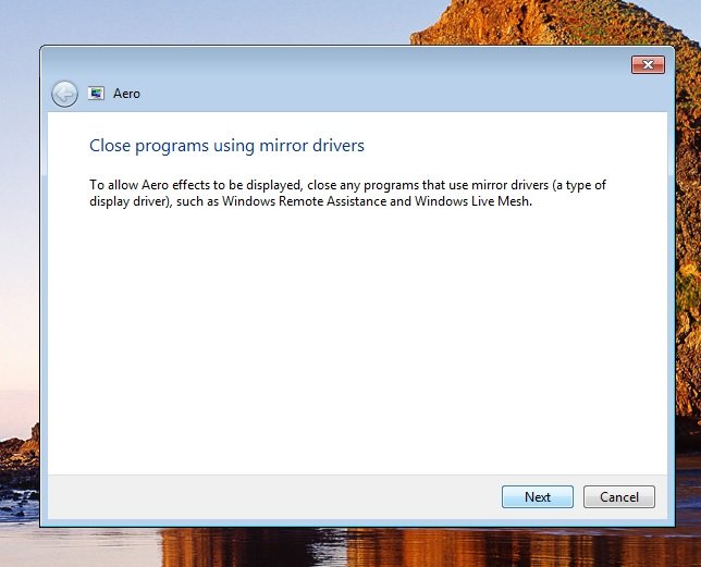
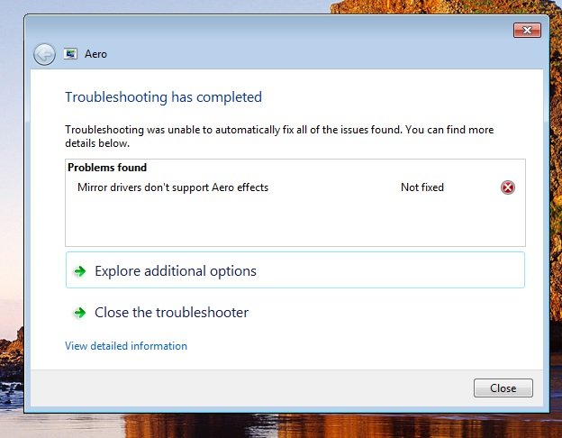
I think it has something to do with our IT company changing over to a more secure backup of the computers. They are now mirroring everything. One more thing that I've noticed changed is when I create a new plane in Mastercam, and right click on it , and go to rename and click. That no longer works! I have to double click on it to rename! I'm not a happy camper!!
-
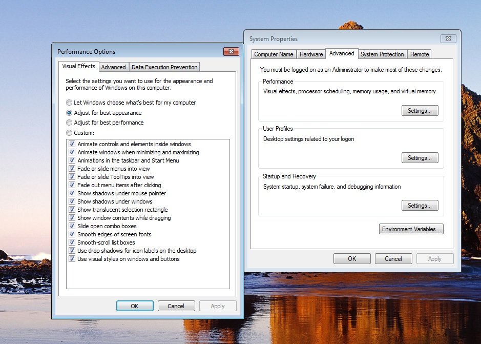
Yes, I don't see the thumbnails. It's light blue now, don't remember what it was before the change. Windows 7 Pro.
-
ME TOO! It drives me crazy - ALT S I use A LOT!
-
The latest Windows update has changed a few things on my computer!! The taskbar on the desktop has changed colors, and the open programs no longer display the thumbnail views! Anyone know how to fix this?? HELP...................................
-
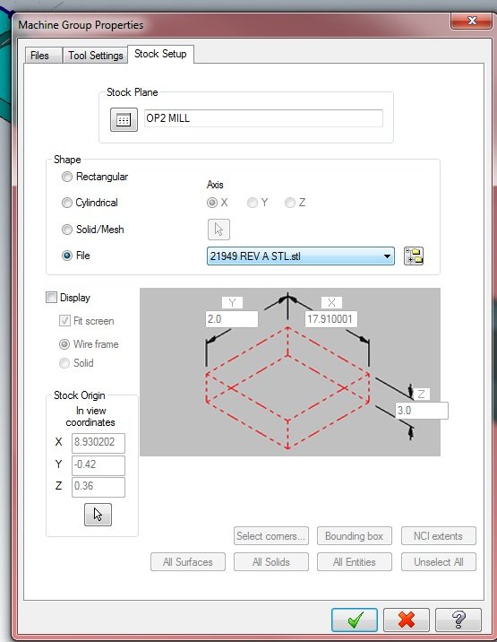
I got it to work by saving the STL file externally, and choosing to use a file, instead of Solid/Mesh.
-
Thanks for replying. The error message says to decrease the STL tolerance. (Which I did try), It's also NOT a tiny part. Overall length is 18" This is the 1st time I've tried using an STL from a prier operation to verify. This part is more complex, and I wanted to make sure I get all the features machined. I've also looked into doing a stock model, but, that is another feature of Mastercam I've never used.
-
I have a part that I want to verify using an STL file saved in operation one. When I tried to verify the first tool path in operation two, I got this error message. Stock volume is too small to display. Increase the stock volume or decrease the STL tolerance. Anyone know how to fix this???
-

Is there a way around Solidworks and Mastercam
Roger replied to mike561h's topic in Industrial Forum
I'm not sure if I would question it, IF they used the hole wizard to do a taped hole............. -
Is there a way around Solidworks and Mastercam
Roger replied to mike561h's topic in Industrial Forum
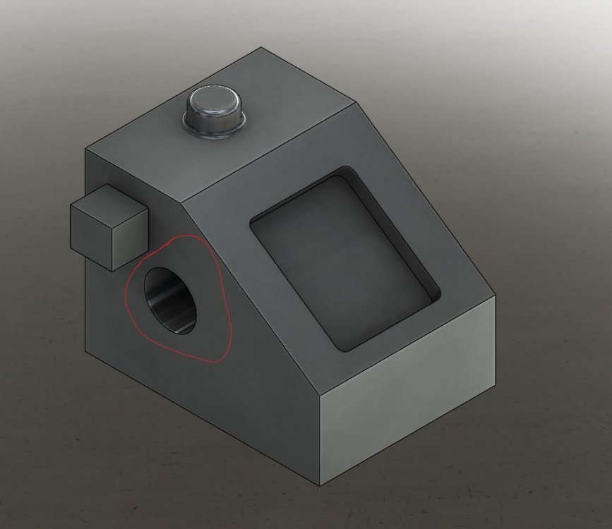
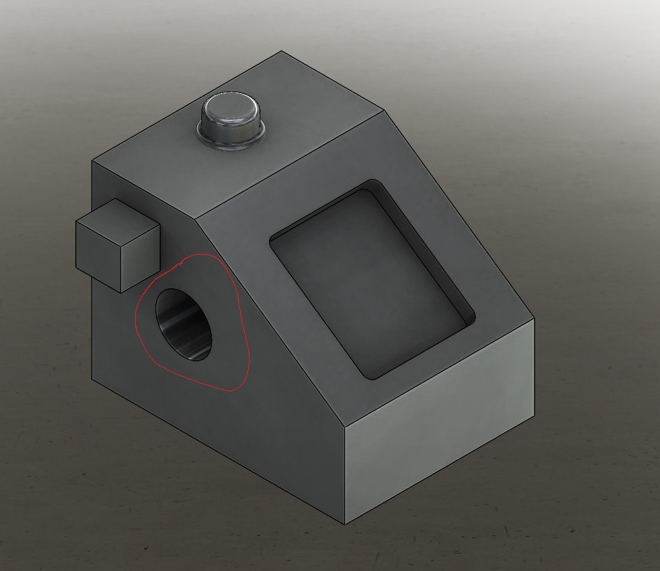
But......If there are questions about the part, I like to be able to see the native Solidworks file. An example of this is the part I'm currently working on. The PDF print has a call out of 6X 10-32 UNF - 2B THRU ALL, and there is another hole (7) on top of a boss that's the same size in the solid model, without any call out. So, instead of looking at their Solidworks file, (If they used the hole wizard), we have to email them............ -
Maybe, Same down arrow, restore default attributes??
-
So our IT guy was just here, and moved everything to the server for back-up purposes.........Mastercam now opens with the default settings. How do I return it to where it was before? Everything resided on my PC before today. Please...............HELP ME..............
-
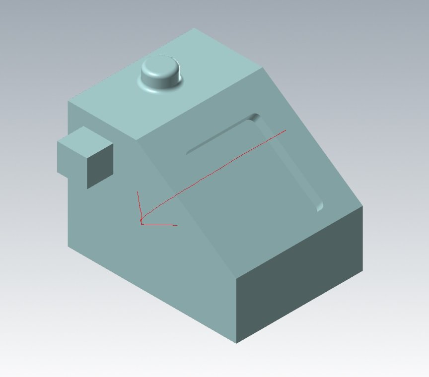
I now understand how your doing your cuts. You do it by inserting a assembly feature. I do it by right clicking on the part I want to modify, and click on edit part. My way it carries through to Mastercam, while your method doesn't. The square boss, and round boss, fillets where added my way. The extruded round cut on the front done your way. As you can see in the follow images. All features show in the Solidworks image, but not in the Mastercam image. Thanks for taking the time to help me understand what the OP was saying.