MotorCityMinion
-
Posts
1,259 -
Joined
-
Last visited
Content Type
Profiles
Forums
Downloads
Store
eMastercam Wiki
Blogs
Gallery
Events
Everything posted by MotorCityMinion
-
X6, pure wire frame. Create a chain for the floor. (machining region). Make sure it's closed and that the opening overlaps the entance edge. Create the avoidance chain on a seperate plane, make sure its closed.DY core should work, entering the cut from outside. Area will helix into the cut from the inside. I'll try the download with IE when I get home.
-
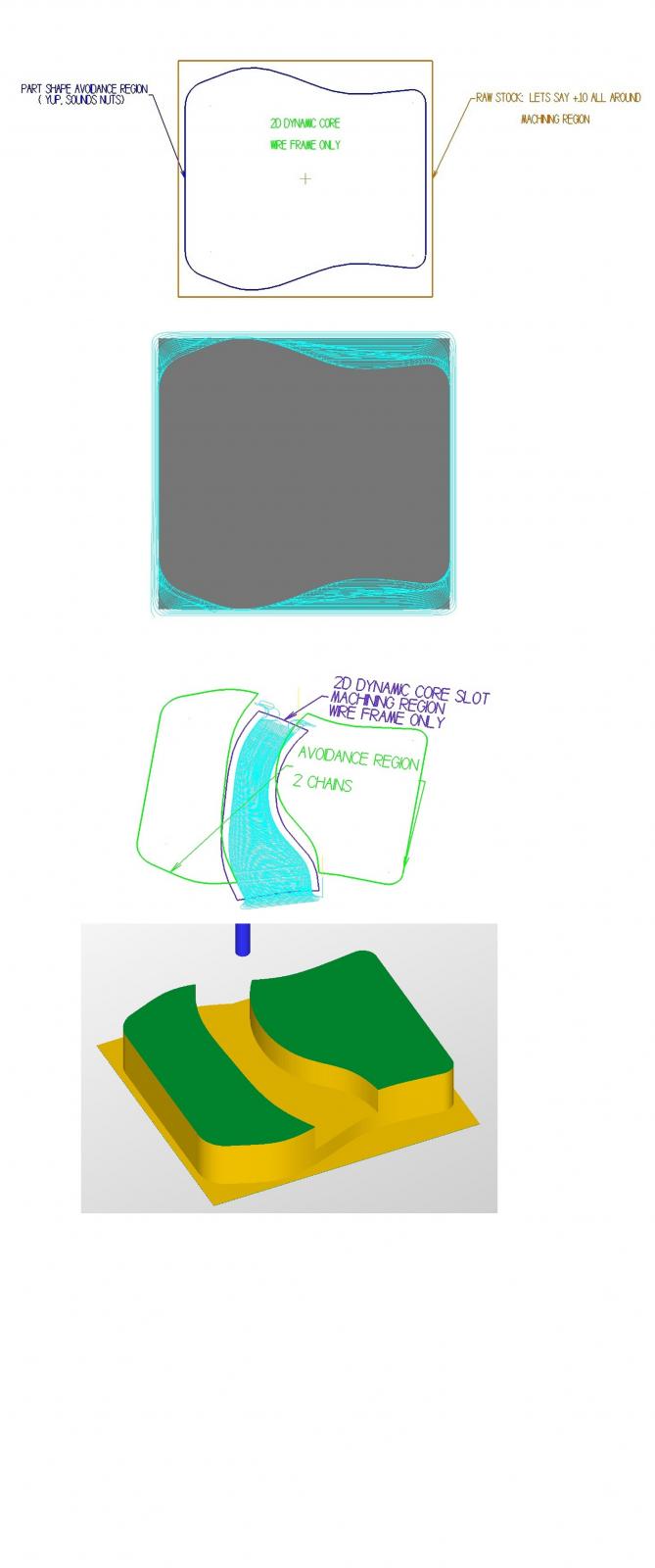
Wireframe and 2D dynamic get along fine. Here's a 2D DY-Core example. Area works for the slot just as well although in this case, peelmill would be the ticket for the slot. Machining region is what we want to remove. Avoidance is the shape we want remaining. 1st screen shot shows the raw stock, let's say a rectangle with stock at +.10 all around. This is the machining region, in brown. The dark blue is the avoidance region, or the shape we actually want. 3rd picture shows the slot through, DY-Core again. Dark purple is the machining region, 2 green chains are the avoidance regions. HTH, MCM PS. Ninja, I tried to download your file and got this message: The server requested a login authentication method that is not supported, using Opera.

-
My bad Ninja. I was reciting from memory. You can still use the surface function. Make sure to make water tight surfaces, turn them into a solid , then boolean remove. Note that in the example I posted, the path is not touching the profile but is normal to it (perpendicular). No X6 here, but the trim solid to surface function sounds like a winner.
-
Sounds like the profile is not flat to a plane. Profile = shape to sweep, path... well thats self explanatory. You can't use a potato chip shaped profile in MC, it must be flat. Also make sure that the path does not bend sharper than the profile will allow without caving in on it self. A 90. deg turn in the path will almost guaranty failure. When you first start the sweep command, in the ribbon bar you'll have 4 options to control the chaining type. Select 4 rails. You'll need 2 profile chains, and 2 path chains. Both profiles will need to touch the paths. This almost never works for me on the first try (X4), don't know why either. In between profile selections, use the blue button between profiles to end the selection. Once you have completed the Across chains, green check mark, then repeat for the along chains. Depending on what your after, the loft command may be a better option for morphing different profiles. Need a pic or upload a file for more specific help. A couple of simple sweeps here. These were not 4 rails though. http://www.emasterca...showtopic=39198
-
 Perhaps a little OT here. With beer goggles on, that is one hideous looking screen shot Greg posted. Looks like anti Fanuc / g-gode. Are these guys the "Apple " equivalent of machine tool controllers?
 -
Thinking out loud here but I've never been able to get a full solids history or anything for that matter with a .sldprt. Recognize (find?) features does a fairly crappy job as well. Good for filling holes quickly, thats about it. I don't think it's even possible to build a complete history. The reverse is true as well. Export a X_B from MC into SW and do a feature recognition and it looks nuts. Takes too long as well.
-
I saw a video about this some time ago. Either Sandvick or Seco, not sure. Anywho.. the HSM toolpaths such as OPTI_XXX, adapative clearing, Volumill, all use this aproach when they can. AS far as 2d, I have not seen an easy way to acomplish this. Modify the geometry (CHAIN), then use a staight on entry will work but that is way too much hassel for most jobs IMO.
-
From the top view pictured, that bevel is fairly steep. I have limited access to chamfer mills and by the time I've completed my Lewis & Clark, looking for the tool, getting one ground up or ordering it, the program is written and ran. Flowline on that surface for sure. Now if I had a production run of those parts, new tools would be the way to go, but for one or two parts, I know I'm not getting out of that chair for tooling.
-
I'm guessing that the part your trying to cut with SF Contour has faces around the perimeter with different slopes and or edge geometry at the top. The reason the tool is hopping around is because it is trying to cut tangent to those faces at the top 1st. As you've found out, extending those surfaces above the part will smooth it out some. Here's how to smooth all of it out. Knowing the radius of your tool, extend all those faces well above the part by at least the tool radius. EX: .06 rad on tool, extend your surfaces by at least .07. To extend them, copy the original surfaces to a new level. Use the untrim feature on every face. Extend all those faces well above the part. Now, trim them all to the same plane. Next, extend those surfaces so that they go through the adjacent surface completely. Trim those surfaces to the adjacent surface or edge curves that you create. If the top edge has a rad on it, you will have to get creative and create vertical surfaces in that area that will work. When your satisfied with the results, look at the surfaces closely and make sure they do not overlap. Now when you program the toolpath, include all those newly trimmed surfaces and use the depth limits in the toolpath, of course setting the top to Z0.0. You can also use the edges of the surfaces, create curves around them, offset the curves inward by a amount greater than your tool nose radius then extrude new faces upward. This method can produce dummy drive surfaces much quicker depending on the geometry. BTW, using dummy drive surfaces can be an excellent way of controlling how a tool enters and exits the cut without using directional controls or tangential line length extensions, which can easily crud up a pristine tool path. If this sounds like to much BS, set your depth limits to start at a negative value that is greater than your tool radius (for SF Contour) and keep adjusting the depth until you get uniform results. Program those upper faces using a different strategy, say blend , flowline, parallel and so on also using depth limits. Using SF Contour, your going to get different surface finishes on the faces depending on the slope anyway. In most cases, no single tool path will give you uniform results everywhere in the same operation. If your going after sweet looking finishes, toolpathing the faces individually, piecing the program together with multiple operations may be your best/only option.
- 7 replies
-
- 1
-

-
- Flowline
- Surface Contouring
- (and 2 more)
-
Model geometry Breaks apart between rotations
MotorCityMinion replied to ashjo16's topic in Educational Forum
Yes, happens quite often in X4. Usually after I've done quite a bit of work. Hit undo, then regen display list, or restart MC and all is good. -
Rick, I've been wondering about that also. I can't find a easy button for that anywhere in SW. HSMWorks created a stock model and had the capability of offsetting all the faces, but still would not create the geo. I really dislike drawing in 3d space with SW. +1 to MC on both subjects.
-
Profiling a radius with back side of key cutter
MotorCityMinion replied to pwolfe's topic in Industrial Forum
The keyway cutter WILL work. No custom tool is needed. If the geometry is circular and consistant in size throughout it's path, FLOWLINE is the ticket. Surface normals must be correct. Use the directional controls to lead-in and lead-out. The keyway cutter will cut with both sides of the cutter without shifting geometry or doing any wierd mathamajical calculations. If only the leading edge of the cutter will do it, something else is wrong. -
HAAS 4th axis tail stock CAD model needed.
MotorCityMinion replied to danielm's topic in Industrial Forum
The Haas tail stocks are decent. They also happen to be very east to model. Get to it. "it will hold a +/-.0002" part after part for DAYS!" Either they got better or you are extremely lucky / need new mic's. Our newest ones (2007 vf4's) can't hold that reliably, and our older ones certainly can't come close to that. Thermal expansion and back lash are hideous. Like James said, they have their place. 'you are calling many colleagues idiots' Agreed. I like those machines and know what work not to put on them. San Diego CadCam, does this mean you don't do business with the Haas crowd? What would your customers think if they saw this post? Here are some pics of what this "Half A$$ American Sh**." can do. Stainless mixing paddle for a Half A$$ American Ordinance manufacture. http://www.emasterca...appy +holidays. -
Helical Solutions and Volumill have a calculator available as well, with a established material database built in. There is even Material info on the selected materials. This thing is cool. Insane SFM's, or so it seems. Volumill appears to use a larger entry rad ( rounding radius), perhaps a bit smoother toolpath as well, opposed to what your used to seeing now. These numbers should still be in the ball park for MC. I Don't have access to either the tools or Volumill. Check it out at .... http://www.millingadvisor.com/ They claim: EX: Stainless PH at 300 HB. 5/8 dia., 5 flute at 1.25" ADOC and .044 (7%) RDOC Conservative: SFM = 676, RPM = 4126, IPT = .0047, IPM = 97.63 Agressive: SFM = 826, RPM = 5043, IPT = 0058, IPM = 145.85 The numbers for P20 are just a little faster. I can't see both of these companies combining R&D, sticking their necks out like this in tandem and generating a bunch of nonsense. It's definitely worth a look.
-
" nobody starts a business with 20 cnc's" Agreed. That's what makes the Haas attractive. Decent starter machines and easy to learn. Most of our Haas's are worn out and have various problems that require work arounds but if 1 guy runs 2 machines and programs at the same time, those machines are making money, period. Could we make more? Sure and I'd rather be doing it with 2 Makinos, but it is what it is. I only get to use our Makino S56 for finish work and even with a 20k spindle we're still short on rpm's for some of what we do.
-
I did a quick test using the above scenario. In peelmill, the rounding radius must be larger than the step over so..... 1" tool, (AJX) Axial DOC at .03, .45 stepover, .46 RR. required a 2" wide L shaped slot. At 2" deep, time 55 min. to rough. A .50 bull em at 1.0 Axial DOC., 10% Radial DOC., .15 rounding radius only required a 1" wide slot. 5 minutes to rough. at a conservative 117. IPM. Enough said there. I can't think of a single scenario where a feed mill would out run a bull em in the 2d HST. Answered my own question. To be fair, If i had a 12mm 4flt Frasia HFM, the time would be under 15 minutes according to their suggested S&F. Fraisa users, I'm calculating this at about 720 SFM and 624 IPM. Is this correct? Seems a little fast for that tool. IDK
-
The Indexable 1" AJX we have has a very narrow range that you use for helical entries, but other than that it's been a great tool with the old school tool paths. Inserts last a long time and the length to dia. cut ratio that this can achieve is impressive as well. Quick hijack. I thought I'd ask here because of the experience with these tools. Are you guys using the feed mills with the 2D HST tool paths? How about 3D Opti tool paths? What's the typical step over with these tools in this scenario? Axial vs Radial chip thinning: Can we expect a longer or shorter run times with the feed mills in the HST tool paths? I'm thinking parts with shallow part geometry / slopes would appear to be the most beneficial scenarios for this type of tool. I have a job coming up, A2, L shaped part that is going to lose about 75% of the material when finished. ( 9 x 5 x 4, 10 parts ). I was thinking about using 2D HST peelmill with the 1" AJX, 45% step over and cutting a 2" wide L shaped channel from both sides to get rid of a big chunk of this. The powers that be are making me mill this. (Should have made 2 parts from 1 blank) Any thoughts about this milling strategy are welcomed.
-
"For example, I never, and I mean NEVER, select points to drill/ream/bore/tap holes. I ALWAYS use the "entity" option when selecting holes, that way I can't accidentally snap to the quadrant or midpoint or whatever. I don't care if there are two hole, it's "entity-window." It ALWAYS finds the center of the hole." A few guys at my place were thought by less than adequate MC operators. 1st thing they start doing is deleting the hole dia's in the drawing they receive and any 3d entities that may be present. ( to dumb to set the chaining options to 2d) If they start a drawing, they use points. This is because the default for selecting holes grabs the point without selecting the entities tab. Almost as if the word entities was Greek. Seriously pi$$e$ me off. They ask about circle milling or helix bore, I make them draw the dia's again before I show them anything. Call me over for help on a tool path and you better have enough info in the MC file to describe the part, or else the tongue lashing begins. They can't use the level manager, think in 3d space or use any other view than top. Extending geo instead of using lead-in / out irks me just as badly. Ok, enough ranting. Learn how to use the level manger and copy, change entities colors, and use the masking features prior to making a big move during xform or any other feature for that matter.
-
Our Makino has spindle start and stop buttons adjacent to one another at the very top of the control panel. After a tool change the spindle is orientated and locked. You have to press spindle stop to unlock the orientation. This machine is used primarily in high speed applications. One guy was in a hurry and blindly reached up to release the spindle lock. At 18k, most of the pieces were never found. I edited the warm up routine to end with S60 and add that to the end of my nc files for that machine. Note: the warm up programs were supplied by the machine tool distributer, they should have known better. Same machine, HSK tooling. Machine USE to alarm out if a tool was put into the spindle out of orientation. It would clamp the tool either way, the wrong way causes the tool not to seat properly and run out about .020. The alarm function no longer works reliably. Put a tool in the wrong way, running high R's and the machine sounds like a hurricane. Only 2 guys in the shop touch that machine now. I S60 and M19 that beast every time I open do anything manually on it..
-
Bring solidworks file in to mill?
MotorCityMinion replied to astroboy907's topic in Industrial Forum
Welcome to the forum. You have a long road ahead of you. Pleases read the following. http://www.emasterca...showtopic=67968 http://www.emasterca...topic=69688&hl= There are tons of free videos and tutorials available. Here's one example. http://www.cudacount...ercamx_toc.html The content available for purchase here (in the store) covers much more. (Mods. Please do not remove the last link posted. It's legit and helpful ) -
"Leave .080 on walls." Enlighten me. Why .080 ?
-
G01, G81... As long as your getting the right retract, what would the differences be?
-
" Which step am i missing while importing the model ?" On the top tool bar go to Settings, Configuration, Converters. Toggle the box for edge curves. They will come in when you import the file, every time you open a new part. Tool late for that. Use it in the future. BTW, you should be able to just open a new file by selecting the inventor part file without using the import function. For now go to Create, curve, curve on all edges or curve on one edge. Preferences for creating curves have been covered many times in the forum. Search is your friend. You can also chain the solid without the wire frame geo but this can be tricky. When creating a new tool path, at the top of the chaining dialog box are 2 tabs, one for wire frame and one for solids. Mess with this some.
-
Parallel is stabbing (bumping into) the edges of the circular feature. It's a easy tool path to apply almost anywhere but really isn't suited for everything. Your going to need a circular tool path to get that nice looking. The blend tool path for the star only may be a bit too advanced for now. If you don't understand the suppression or surface extensions, that's fine. Use the hst spiral for better results without too much grief on your end. Cut in one direction only, don't zig zag if possible. For an easy SF Blend to cover the whole part, create a circle at the outer perimeter and break it where you want the cutter to start. Put a point in the center. These 3 entities will make up the 2 blend chains required. The order and direction in which you select the chains will determine the path that the cutter takes. Yes, the point is used a chaining entity. Not hard at all. Use the spiral option. Play with along and across and 3D. This is an awesome tool path. Material and cutter type / quality will dictate the feed rate.
-
Here's how I might do it. Fill the star (suppress it if created in MC) then use the HST Spiral or SF Blend to finish the circle. Independently finish the star with SF blend, which may require several operations, or... yuck, a scallop path if you want to get it in one op. If at all possible, extend the surface edges of the star up above the circular face to use as a smooth lead in for the cutter and help to avoiding rolling over the edge and ruining the definition of the shape. Choose a blend direction that goes along the length of the points, not across. Your blend chain may look like an arrow with a point in the center of the base. (3 entities). Repeat for the other 2 legs of the star. One way cut if possible. HTH, MCM