MotorCityMinion
-
Posts
1,259 -
Joined
-
Last visited
Content Type
Profiles
Forums
Downloads
Store
eMastercam Wiki
Blogs
Gallery
Events
Everything posted by MotorCityMinion
-
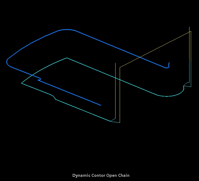
Mig, It works with Dynamic Contour no problem. Just select the open chain. Settings in the tool path were straight forward. See picture. It will Multi pass as well by defining multiple step overs in the finish passes dialog box. In my example above I used Dynamic core mill. My bad. I mis read your inquiry and it was asking about Dynamic contour. The part shape is the blue chain and was closed. This was my avoidance region. The purple chain represented the raw material, "Machining region". The end result was an open pocket style of machining, entering from outside the raw material. I tried that same part above, copied the tool path, omitting the closed profile of the bass body, and used a open chain (blue) for the avoidance region, purple was the machining region. I then selected a custom entry. Point failed, single line failed , circle failed and a closed chain failed. Every time I received the error "Open chains will be ignored (custom entry not chosen". Yes, I choose it every time and entry speeds and feeds were set. Either Dynamic Core mill does not support open chains or I'm way off here. The video does not show the chaining method. MC help files: Dynamic Contour—mills material off walls supporting closed or open chains. Dynamic Core Mill—machines open pocket shapes or standing core shapes using the outmost chain as the stock boundary. The tool moves freely outside of this area; the inner chain defines the limit of the toolpath. Kieth. I could not get Dynamic Contour to rough in that fashion. How did you do it?

-
I'm lurking as well. With X7 soon to be here, were going to need some new HLE's. Hey corporate, you listening?
-
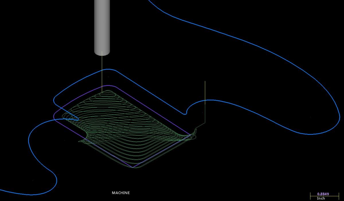
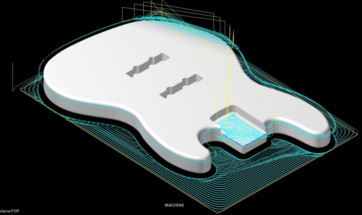
You can treat it like an open pocket Using Dynamic Core. Create a closed boundary that represents the stock. See attached picture. The second picture shows the same part using a Solid. Opti-core and Opti-rest, using the same boundary as a containment for the neck recess, which is an open pocket. Edit: My bad guys, that first picture should have been named 2d High Speed Dynamic core - open pocket.


-
"How does the 3D PDF work? I press the 3D button and nothing happens. I already restarted MasterCam and rebooted the PC. Thanks in advance." TK, this is bad a$$! You need to have solids or surfaces visible. I tried it with wire frame and it farted. As dumb as this may sound, you do have Adobe pdf installed, correct?
-
Just messin' with ya K2. Seriously though, I thought perhaps there may be some unseen consequences other than not posting a roughing or pre-drill op. "BTW.. MCM can you share the vendor name for these Superman taps? They sound really handy.. rofl.." http://www.emuge.com...ts/me_1102.html I'll post just one op when.... I feel the need to eyeball the code. Run it through Cimco Backplot to get a second opinion. Programming and running the part simultaneously.
-
"It can be very detrimental if, for example, you miss a drill op before tapping......" Um, i was actually inquiring about situations other than the obvious. We use Superman taps here, so that's not a problem.
-

Hydraulic Holder Failure
MotorCityMinion replied to MotorCityMinion's topic in Machining, Tools, Cutting & Probing
Newbee, clever to think of that. Rgh at +.005 with a .156 ball in a collet on a Haas, no problem. Off to the Makino for finish work. 2.0mm is the smallest internal rad on the part so the rougher had the cusp scenario covered. 3.5mm ball, 6mm shank at +.002 in the hydraulic holder, 3.0mm ball finish in a heat shrink holder. We use OSG tooling for finish work and the gussets are very small with these tools, there is very little clearance. Stock awareness is a priority. I thought there may have been a burp in the code but backplot, verify, and Cimco backplot with solid simulation, NC code, show no erratic moves. This also occurred while milling a horizontal feature with only .005 stock on it. Copy , paste the op from from semi finish to finish and change a few parameters done. The finish path was pristine. By all rights, this tool should have snapped but it still looked good enough to rgh with. Funny how you can accidentally plow through a part and not have a tool snap. ( Is this how adaptive clearing got stated? ) LOL, who hasn't fat fingered a feed rate and knurled a flat face at some time in there career? Laser weld , rgh again, then finish. No biggy on the rework but this happen on two different parts, different terrain. Now I'm spooked. -
Recently I have had 2 holders where the tools are pulling out. A.25 and 6MM dia. holder, while doing finish operations, HSM, .005 max stock, not heavy machining. We use e-mills with an H6 class fit. These tools have not been crashed nor do there appear to be any leaks. Tools were fresh, holders looked clean. Lock screw bottoms out, but I've read that this is normal. Any clues or tips? BTW, these are fixed dia. holders.
-
"Suppressing the warning could come back to bite you latter." OK, now I have something else to worry about. How may this action be detrimental?
-
'View Sonic VX2253, connected via a HDMI cable. Its a 22" LED full 1080p, with a native resolution of 1920X1080. Nvidia Quadro 600 (1GB DDR3 with a DVI output). His PC has a Intel Xeon chipset, E3-1225 v2, & 8GB ram" This is more than acceptable. You should be able to set the chord setting to .0002 with no graphics distortion. If your working with a large amount of cad data, it can slow you down but will stabilize when your done rotating or zooming. James is talking about windows themes and fonts. Try it with Windows 7 basic or Windows classic. Keep the system font average, nothing too wacky. Right click on the icon that launches Mastercam. Select properties. Put a check in the Disable visual themes and Disable desktop composition boxes. Select apply then close the dialog box. Start MC and take a look. The image you posted appears to be ghosted or sitting on top of a duplicate entities. In the Utilities toolbar, there is a icon that looks like a paintbrush / flashlight ( WTF is that ). The orange icon named Regenerate display list. Use this to force a screen refresh and see if that helps. In dozens of different set-ups, mostly low end, I've never seen a straight line not be straight. Do your circles look like ovals when viewed from head on? If so, your resolution settings are off.
-
Mastercam X4 Solid Face Error
MotorCityMinion replied to polarbeartaglia's topic in Educational Forum
Lets get you un-stumpted. Open up the Inventor file directly. IF that's a no go (version compatability issue), use "save as" from Inventor as a para-solid or step file then open up that file. -
T-SLOT MILLING OF UNDERCUT BY SURFACE ROUGH CONTOUR
MotorCityMinion replied to beginner1977's topic in Industrial Forum
Flowline stabs that part. The width is not constant, it tapers from one end to the other significantly. Looks like a a multi axis path is required here. -
How did you get started?
MotorCityMinion replied to Pilot Plant Supervisor's topic in Industrial Forum
Aircraft jobshop, late 80's. Manual G-code on a lathe, BP and DP work cranking handles. -
can i change anything on the setup sheet on mcx4
MotorCityMinion replied to drogers's topic in Industrial Forum
You may have to download language.dll directly from the source. No install, just drop it in the chooks directory/folder where X+ was installed. Your probably seeing German text. -
aRC FilTEr in the tool path settings. Convert as many splines to arcs as you can first. Any part, not just solidworks files, can create issues like this.
-
Is this tool path ready for the masses? Granted, a fundamental understanding of which tool path to use with a certain type of terrain and knowing what switches control the variables is required to complete a part in a successful manner that produces results which include timeliness, dimensional stability and cosmetic appeal but some of what I’m seeing here is less than satisfactory. “:crossing fingers: while mold is cutting” Making statements like this to my boss on a one piece jobs is entertaining. "I have a containment boundary and I tell it to sit inside but NOOOOOOOOO it goes outside the containment boundary!" Man up, this is how they do it in France. "As far as your gouges go, go to your Linking Parameters - Leads - Make sure Horizontal Arc Entry and Exit are at 0.0. Any other value in those two boxes will cause a gouge now and then." I’d set my op default to 0.0 for this data field then put tape on the monitor over the location of that dialog box. "The problem comes out when using the preserve 3D passes. It doesn't like vertical walls with sharp corners. Tried closed offsets and upper to lower and would get gouges (not always)." Trying to preserve 3D passes in a 3D tool path, the nerve of some people! "If that doesn't solve it check out your transition parameters. I had it set to tangent ramp - gouge. Went to Ramp - Angle - 30 - gouge. Angle - 20 - gouge. Angle - 10 - no gouge." Found the sweet spot! Here is another op default to set. Get some more tape. "But, the gouges on the vertical walls aren't really gouges, their probably the fact that the tool is tracing up those walls to the next cut. To eliminate this, you need to change the percentage of the tool diameter on the Keep tool down within on the Cut parameter page. Too big of a percentage causes the tool to trace up the walls to the next cut. Lower that percentage and the tool drives up and over these walls to the next cut." I agree with this statement although it is not germane to this tool path. I came across this situation last week while using SF Contour and SF Parallel on the same faces in a curvy progressive die component, CPM4, using a 3.5mm ball and 3.0mm ball. The vertical walls appeared to have chatter in them. The solution was to semi-finish at plus .002 stock and use a slower feed on the semi- finishing tool then switch to a smaller diameter tool for finishing as this allowed for a smother entry into the vertical wall. Only two pieces on this job so I didn’t have the time to narrow it down as I probably could have tried down milling with the smaller tool first. Not enough chip clearance and flute length on the precision OSG finishing tools could have been a factor as well. “I am cutting a die cavity and would like to start on the bottom and cut up. Is there a setting that would allow me to do that with Surface High Speed Hybrid toolpath.?" “That would be a good thing to change with X7.” According to a PDF I came across: 3D HST HYBRID. Optimized cut Order. In Mastercam X7, 3D HST Hybrid Toolpaths now include a new Optimize cut order checkbox on the Cut parameters page. This option defines the cut order Mastercam applies to different cutting passes in the toolpath. Now all we need is Optimize Containment boundary , Optimize Horizontal arc lead in , and Optimize Ramp Angle check boxes. Perhaps some of the new beta testers could comment on this as other changes to the toolpath may be in the works.
-
Tool Ø recommendation to cut a slot using dynamic roughing...
MotorCityMinion replied to Watcher's topic in Industrial Forum
I believer the default rounding radius in Volumill is 45%. Although very smooth it's not suited to all conditions as this forces a cutter diameter selection small enough to fit those parameters, may lead to a diameter to length ratio that is less than optimum, and may require multiple axial passes as well as more rest milling. It can be over ridden to suit the tooling on hand. Volumills allegiance with Helical Solutions has produced a speeds and feeds app that boast some pretty impressive data. IMO, it's worth a look. http://www.millingadvisor.com/ Although I don't machine the high temp alloys, Chris Rizzo recommended a 30% rounding radius as a rule of thumb with this style of machining and it has worked very well in both MC and Cimco/HSMWorks products for me. -
can i change anything on the setup sheet on mcx4
MotorCityMinion replied to drogers's topic in Industrial Forum
I was less than help full in my last response to one of your post and I apologize for that. I'll try and make it up. To screen capture: There should be a print screen key on your keyboard, top row to the right on a most keyboards. This will capture the screen image and copy it to the windows clipboard. Now you can open up MS Paint and paste the image from the clipboard. You can now crop and resize the image. This works with any screen image, not just MC. You can also paste it to your favorite image editor. Photoshop, Paint shop pro, what ever you choose. Another way to do this while in MC is to go to the screen tab in the top row of MC. In the drop down menu, the very last item is the "Copy Image to Clipboard" selection. This will do the same thing as the print screen key on the keyboard. A third solution that will cover both of your inquiries. Use the X+ setup sheet. This an add on app that is very popular among the MC community. It's totally customizable. It will also screen capture, allow you to use a company logo and do a few other cool tasks. Get it here. http://www.emasterca...ds&showfile=216 Learn how to use it here: http://www.eapprenti...-mastercam.html -
problems with my feedrates when milling a pocket
MotorCityMinion replied to drogers's topic in Industrial Forum
OK, I've watched this for half the day now and bit my tongue. Now Makers Mark is talking... "i have noticed that when i cut a pocket in mastercam and pull up the g-code the feedrate for the pocket starts at F0 and does not exceed F.01. when i cut contours or drill holes and so on the feed rates are right. I do not have the feedrates on my tool manager because they vary to often and im working with my own pesonalized tool list. in my tool list the feeds are set as zero because the calculated feeds and speeds are drastically to high." Drastically too high relative to WHAT? The machines capability, the material being cut, or the tools capabilities? Please describe the scenario in a fasion suited to that which an experienced machinist can respond to it in an intelligent manner. Apparently, your pesonalized tool list sux. At first appearance, this is not a software issue, as it pertains to you wanting to be the Captain of your own ship and not following any given standards for typical machining practices or guide lines relative to speeds and feeds or the software being used. This crap has already been worked out over the last century, research and implement. I can grab my Bridgeport slip stick or Handy Valenite Reference from the 70's and pull up some useful data that won't smoke the tool or F-up the part. I edit the tool and it works. How about saving that tool data to a new library relative to the material being cut? Not a bad idea. You extended the effort to create your own pesonalized tool list then choose not to commit to speeds and feeds for a given material or specific tool being used, then have the nads to ask why the software cant produce useable code? . WHY? I've never made an edit to speeds and feeds and not have it stick. Get with the program and put something in there suited to the material being cut, anything other than ZERO. WTF? "and my company did not buy this software another one of our companies baught it before they shut down and it was sent to us. so i have no dealer." Um, really, is that an excuse? The dealer does not have the capability of raising your IQ. "i am running mastercam x4 and im still confused about the post. wat is post and were can i find wat post i have" At this point in the conversation, the editing of tools in the library becomes a moot point. http://dictionary.re...browse/moot?s=t -
I'll wait till I'm sober to respond to this one.
-
Thinking outloud here. Project the a grid of curves/sketch to the faces before flattening them in SW then analyze the curve length.
-
HAAS VF3 YT/50 Spindle Motor/Gearbox issue
MotorCityMinion replied to ERIC14779's topic in Industrial Forum
Warm up is required. The waylube cools the spindle. A line was probably pinched during assembly. Were the tools warm to the touch after running them for a while? Did they "pop" when tool changing? The spidle probably siezed when it faulted? -
Opticore Not Obeying Containment: MC X6
MotorCityMinion replied to ccs86's topic in Educational Forum
Yes, I believe that's exactly how the logical option for boundaries should work. There is a major problem with tools/options being used in one toolpath not functioning or behaving the same way in another toolpath. Granted there probably are some valid reasons for this situation, but in most cases, it seems like more BS and lack of effort to correct the situation before releasing it to the public. Try explaining to a foreman or a trainee why I can use this option here and not there when both scenarios should be valid with the same option. IMO, the same can be said about check surfaces as well. Some paths use em, some don't. And those that do can often freak out the toolpath in the check surface region and create less than satisfactory motion on entry and exit moves. Granted other CAM systems I've seen can exhibit these same conditions to some degree so this isn't a unique situation we're talking about here. -
plunging ramp or helix
MotorCityMinion replied to BOATDUDEGUY's topic in Machining, Tools, Cutting & Probing
The videos are impressive. We have a Makino S56 with the Haimer system but use it primarily for finishing hardened tool steels. We spend quite a bit of money on expensive ball nose cutters and do very little roughing on this machine. But I am going to put a bug in the ear of somebody that runs a rather large shop in the area and has the resources to experiment with this stuff. Chances are , he may already be aware of them. PS: Swift-Carb has a channel on youtube, open to the public with over 20 vids. You just half to go to youtube directly and search for Swift-Carb -
plunging ramp or helix
MotorCityMinion replied to BOATDUDEGUY's topic in Machining, Tools, Cutting & Probing
Hmmm, this video is private in IE and Opera. Even the youtube link blocks me. Looks like I need to create an account. Ok, I went to Youtube directly and it works fine without a log in.