Guyinthedesert
-
Posts
376 -
Joined
-
Last visited
Content Type
Profiles
Forums
Downloads
Store
eMastercam Wiki
Blogs
Gallery
Events
Everything posted by Guyinthedesert
-
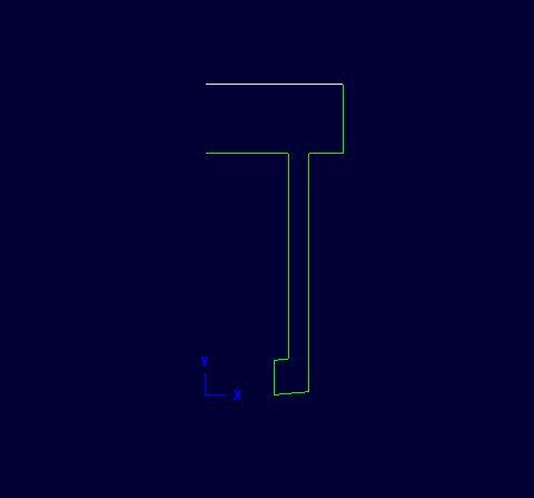
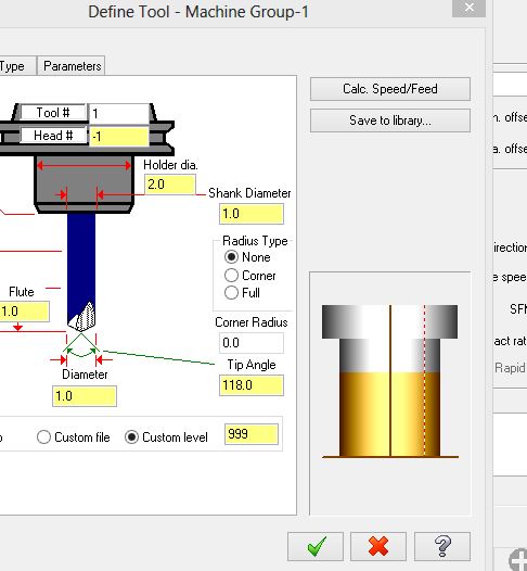
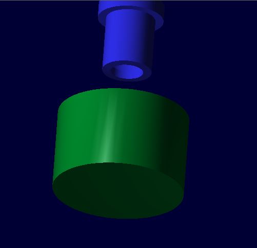
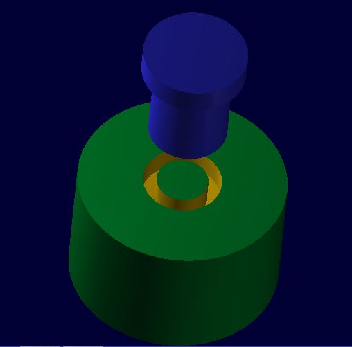
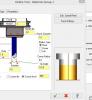
see attached screen shots, #2 is how I drew the tool, just a bar hanging out with the inside tip at 1.000 dia #3 is how the tool looks in the tool manager. It's going to revolve whatever you draw, so it's not actually going to look like a boring bar #1 is how the tool looks in verify. Notice it is hollow #0 is how the part looks in verify, with a 1.000 dia boss left in the middle Hope this helps


-
haven't done this in MC with a boring head, but I use trepan tools for o-ring grooves ( same concept) and it works just fine in verify. I use undefined tool, and draw it on a separate layer.
-
I would leave about .006, then go in with a carbide reamer. It should be a no-brainer. Did you indicate the reamer in? I wish I had a nickel for every time someone came up to me and said "Reamers no good, it's cutting o/s at the top". Then I stick an indicator on it to find .004 runout. Response from idiot set up guy, "Is that too much?" If it's still giving you trouble, ream it .002 u/s and have it honed.
-
on the cut parameters page, have you selected "Wear" as compensation type? On the lead in page, just select perpendicular entry. and start at center. The entry line length box is ungrayed when you uncheck Start at center. (Generally only used on large holes)
-
We've ground it and it didn't present any problems. As far as machining, it doesn't appear any different than any Teflon based composite. First choice would be very sharp HSS tools.
-
I eat Cattle
-
Milling o.d. threads is really no different than milling i.d. threads. Mc's threadmilling cycle lets you select i.d. or o.d. You're going to need some kind of a gage. From your post, I don't get the impression that your doing aerospace work, so I would guess you could use a mating cap as your gage. As far as tables, get your boss to buy you a copy of machinery's handbook.
-
I read and re-read, but I didn't see what diameter tool we're talking about. 3//4 and under I think a 40 taper isn't a problem. 1" is pushing it, over 1" I wouldn't try without a 50 taper. 4" and over I'd go with a 50 taper bolt on. (do I miss those days?)
-
everyone, I get one from a dealer Learning Edition
Guyinthedesert replied to 宏滨 高's topic in Industrial Forum
Thanks, nothing like having the image of a sticky booger in your head while trying to eat a Jack in the Box burrito -
depends on the size of the chuck. I've turned 20" dia 4140 in an old WWII Warner Swazey without a problem. Of course, I never stood in the flight path.
-
We have a Brown and Sharp w/ PCDMUSS. Maybe we just got a lemon, but over the last 5 years it's been down more than up. Turned out to be a real gold mine for the techs at hexagon. But, the biggest problem we've had CMM wise, is finding someone to run it. They all want upwards of $100k to sit and watch youtube videos half the day. Or they get caught smoking grass behind the building. All but one guy we had refused to check anything on a surface plate. ( hopefully, that one guy we can get back as soon as he's up for parole) None of them have had the ability to calculate a true position without pcdmuss outputting it for them.
-
Pros, Cons, Mounting vises on raised sub plate
Guyinthedesert replied to Roger's topic in Industrial Forum
I think you would find your set up much more rigid if it had a bottom plate, so it formed a box, and all the joints were welded, not bolted. We used to have the same problem where I used to work. The larger 50 taper machines wouldn't go low enough. Also, with a table like that, you have the luxury of being able to bolt things down from underneath. On the downside, we all hate riser plates with tapped holes in them. Nothing beats a T slot. We bought several Haas mills that came with Chick setups. Everybody got so fed up with their riser plates they all ended up in a chip can. -
It's doing the same thing here, first index is -72. I tried changing the minimum travel limit to -1 in the MD, stil outputs neg, so I'm thinking it's in the post.
-
What post are you using? Also, is this a 4x or 5x setup?
-
do you have mnisc integer set for positive moves?
-
how are you drawing and defining it? Under tool type, check on undefined tool, then click on file or level, depeding on where you have it drawn.
-
Error says you can't receive messages
-
Ah, many thanks, that was it. I wish I had a Renishaw manual. I had one years ago when I was probing on Fanucs, but with Haas, if it's not listed on the VQC, I guess they expect you to just sit there taking wild stabs in the dark?
-
I've never used the 3 point boss/bore routine before, but here's what I got. I need to probe the O.D. of a casting, however it has a round flange with 6 bosses (for bolt holes) sticking out of the profile at 60 deg intervals. (30, 90, 150, 210l, 270 and 330 deg) I thought I'd try the renishaw 3 poing boss routine. It seemed to work ok, but when I started doing a test cut, I could see it was way off. I indicated the od best I could with an indicator, it was right on in Y, and -.090 in X. Then I tried probing just the X with the X boss routine, and I got roughly the same number as with an indicator. Here's the routine I used; G00 G90 G56 X0 Y0 G43 H40 Z1. G01 Z0.9 F50. G65 P9832 G65 P9810 Z0.3 F30. G65 P9823 A0. B120. C240. D4. Z-0.3 S3. G65 P9810 Z2. F60. G65 P9833 Now, if I change the angles to A60. B180. C300. then Y is still right but X is off .090 the other way. Am I missing something? It almost seems like a bogus calculation in the software, but that seems hard to believe. Any thoughts? TIA
-
I'm not sure what the proper way to do it is, but here's what I do. Change the extension on your old post to something else, like .pstxxx When you go to post the file, now since the old post file doesn't exist, it will say Invalid Post File, and now it will allow you to choose a new one.
-
There are a couple values you need to change in the post. I use the generic Haas 5x trunion post for a trunion with the tilt axis along the X. With a trunion mounted 90 deg. (which is what I think your trying to do), I use the same post, but with the following changes to the post rotaxis1$ = vecx rotdir1$ = -vecy rotaxis2$ = vecz rotdir2$ = vecy
-
When I saw the title of this thread, I just thought he'd gotten his maintenance bill.
-
Whenever I notice a disc is getting a dimple, I just pull it off and regrind it flat.
-
enter at midpoint, no consistency in an array
Guyinthedesert replied to Dana L Johnson's topic in Industrial Forum
can you try using an entry point? -
I get that trying to open SW13 drawings, but not SW12.