Jrygus
-
Posts
116 -
Joined
-
Last visited
Content Type
Profiles
Forums
Downloads
Store
eMastercam Wiki
Blogs
Gallery
Events
Everything posted by Jrygus
-
Just bought this cheap IP Remote Control Camera On Ebay for $70. Made a little plexiglass box in one of the top windows in our new SNK 5 axis. I think it works great. I love being able to watch my programs run, while I am programming. I just thought I would share the result of this test. I have 2 more on order. The Camera is an EasyN. It is sold by LinkDelight on ebay, out of china.
-
We just got an SNK HPS120B with Fanuc 30i. Finally got it all setup. Started to play with it and I get this alarm when i run the spindle. No.2026 Oil&Air Alarm. I cannot find this alarm anywhere in my books or on the web. (with any explanations) Thought I would see if any of you guys have seen this before I get repair guys back in here.
-
You got it Goldorack. I did not see the "Motion > Gap size, retract" setting. Thanks for the help.
-
Turned off "Use core mill passes" and it went away. I would rather have this on, but i can live with it off.
-
I have tried/recreated many different boundaries and no luck. I did try specifically restarting and re-chaining like you mentioned and nothing changed.
-
Opps, I just upgraded to X5 MU1.
-
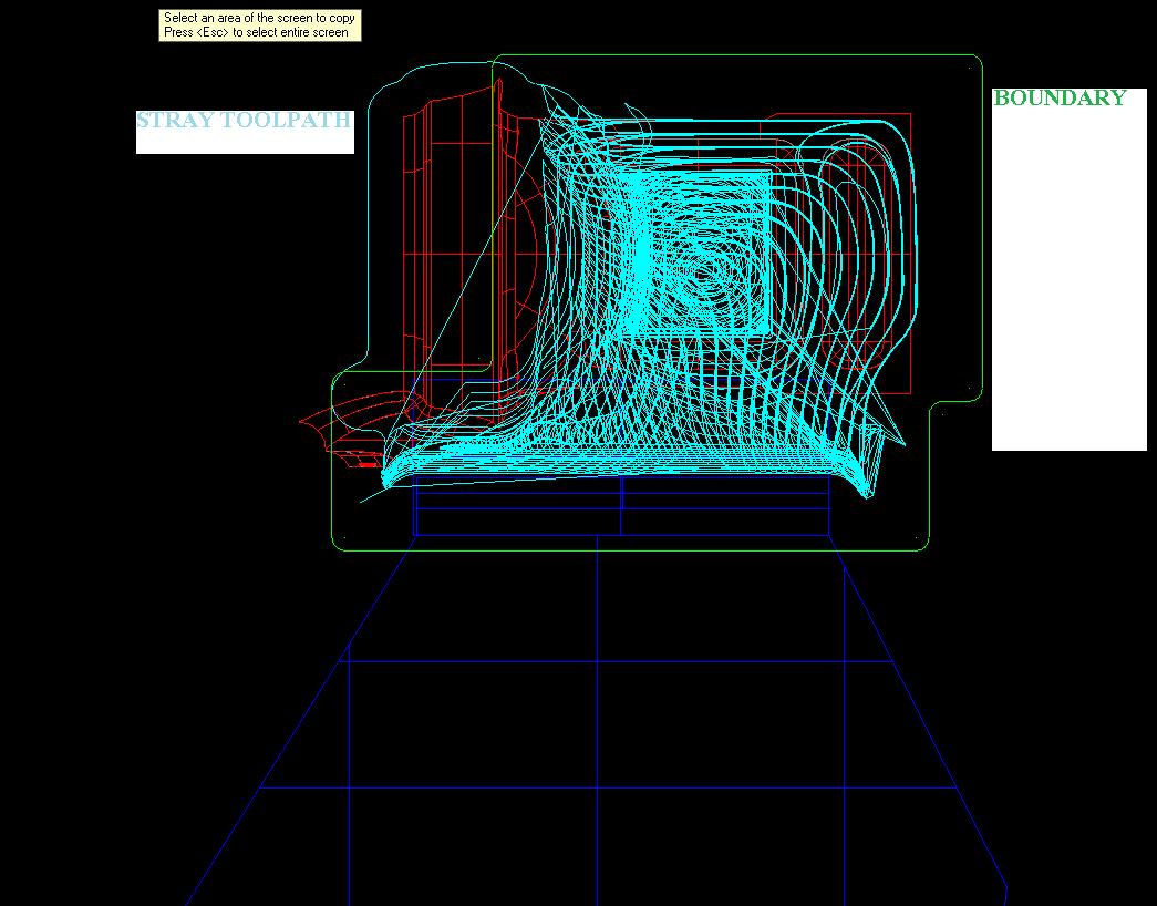
I cannot get my optirough path to stay inside the containment boundary. Is there an issue? I cannot find info about one, or am i just doing something wrong. in the picture the green wireframe is my containment boundary, and the blue is the path that strays outside of it.

-
Thanks Thrash, that works great. I can definitely see using this on jobs with non standard tools.
-
I always use inverse on my Haas. The motion is smoother.
-
The free version of Display Fusion gives you the functionality to 1-click send window to the other screen. You click the mouse wheel in the top of the window and it sends it to the other screen. I find it very handy. http://www.binaryfortress.com/displayfusion/
-
I have yet to get my Haas to connect to Vista or Win 7. XP works great. I would be curious to know if anyone else has made Vista or 7 work.
-
I have had that issue when my inverse feed gets up over the max of the machine. The machine is not going to fast, but the code is like F45000. I increased my increment step a little bit and the number dropped quickly.
-
We have an NT5400. Had to make the change to Esprit. We tried Mastercam for Integrex and Mori NT mill-turn. Esprit has been much better for us for mill turn. Guys on this board have made it work. We could not. I like Mastercam much more than Esprit ( I am a mill programmer) but Esprit handles mill-turn better than mastercam in my opinion. I will get hammered for this i am sure, but i wanted to give you my opinion from my experience.
-
+1 Please Disable trim preview and fix trimming back to quadrants. It's a PITA.
-
Right on Norbert! Disable visual themes by itself did not do it, i had to have the Disable desktop composition on like in your picture. Now it looks like it works good. Thanks for your help. I really needed the setup sheet upgrade.
-
My statement was not meant as a rip on CNC. I know bugs happen and don't mind running software that is constantly changing. I like it actually. I was just a little disappointed the i will have to wait for another release to run a feature that i feal like i already paid for, running of a system that i believe is fully supported. If CNC had smaller updates that happened more frequently so i knew that a fix would be out soon, i would not have an issue at all. As it is, i will be ok with waiting or i have the option to go back to XP, and i am loving the enhancements of X4 so far. So please don't take my personal dissapointment of not getting to play with the a new function of software that i love playing with be interpretted as CNC bashing. I look forward to MU1!!
-
Wow... Thats sucks! I hope MU1 is not 6 months away....?
-
Yes, I am Vista 64. Thanks for the info JP. I guess i wait for the release, then start playing with it.
-
I get no pictures at all. I am guessing it is a video driver problem, but have not been able to play with it yet
-

X4 rollout seminar Part2
Jrygus replied to Jimmy Wakeford from Barefoot CNC's topic in Industrial Forum
I went to the one at Cimtech on monday morning. Rich did a nice job of showing us the new features. Looks like mill is getting some nice additions. Lathe looks like it gets nothing significant. Glad i am a mill guy. -
Use Toolpath Editor and edit point feedrate. You can change section of points as well. It's slow, but it works.
-
Thanks Apps Guy for the help. What i ended up doing was a combination of things. I stole some of your logic to set the L and the P, and then i am using the Drill variables to get my X Y Z. So now my process will be, Create a point that represents the center of rotaion/common on machine. Then in my drill variables i right click and choose X/Y/Z coordinate for each drill variable and select the center of my rotation. This is how my Post ended up fmt L 4 lvalue #L value for G10 2 or 20, 2 for 54-59 and 20 for g54.1 p fmt P 4 pvalue #p value for G10 1-5 for G54-G59, and 1-> for g54. p fmt X 2 wsetxval #X value of center of rotation fmt Y 2 wsetyval #Y value of center of rotation fmt Z 2 wsetzval #Z value of center of rotation if drillcyc$ = 14, [ if workofs$ < 6, [ lvalue = 2 pvalue = workofs$ + 1 ] else, [ lvalue = 20 pvalue = workofs$ - 5 ] wsetxval = peckclr$ * -1. wsetyval = retr$ * -1. wsetzval = dwell$ * -1. "G0 G90 G10", *lvalue,*pvalue,*wsetxval,*wsetyval,*wsetzval, e$ ] This is how the cycle looks in MC For now, the output has to be edited down to just the G10 lines, but it eliminates the creation of them manually. Thanks again for the help.
-
Thanks Apps guy, I think i see how you handle it. I want to see if i can figure out my drill cycle, then if i can't, i will see if i can setup your method. Thanks for the help.
-
I am trying to modify Mpmasters custom drill cycles to create my G10 lines. I have most of it worked out except for my X,Y,Z, values. This is what i have so far Two Variable defined fmt L 1 lvalue #L value for G10 2 or 20, 2 for 54-59 and 20 for g54.1 p fmt P 1 pvalue #P value for G10, 1-5 for G54-G59, and 1-> for g54. p And my drill cycle looks like this if drillcyc$ = 14, [ lvalue = peck2$ pvalue = peck1$ "G0 G90 G10", *lvalue,*pvalue,*pfxout,*pfyout,*pfzout e$ ] What i need is the value of the pfxout, pfyout and pfzout to be the negative value of what they come out as. I have been trying to multiply them by -1 to change the sign, but i cannot seem to affect them, or set thier value to another variable. If anyone can help i would appreciate it.
-
I had the same problem. Check in the operations manager then the stock setup. The "Stock View" affects your stl location. Should probably be set to TOP. I believe another member (Colin) wrote up a post on this topic. You might want to search for that.