


Chally72
-
Posts
499 -
Joined
-
Last visited
-
Days Won
32
Content Type
Profiles
Forums
Downloads
Store
eMastercam Wiki
Blogs
Gallery
Events
Everything posted by Chally72
-
Unified toolpaths can be locked to 3 axis on the Tool Axis Control page and posted out and run on 3 axis machines
-
We're aware of how useful this can be elsewhere and are looking at how we can implement it. That's why we placed this edge feed rate control in the Tool page rather than sequestered away in a threadmill specific page.
-
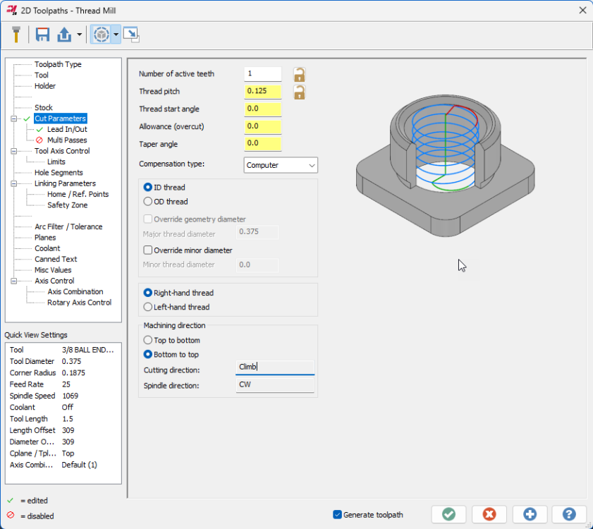
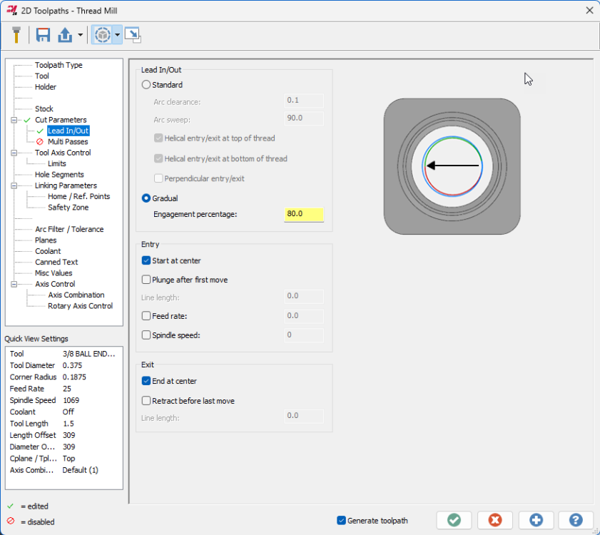
AMW, I'll pass this thread on to the product owner. Just a note that 2025 has received a bevy of Thread milling enhancements developed in concert with tooling manufacturers. Check out the Gradual entry on the lead in/out page to reduce shock load on engagement and the expanded entry/exit controls and speed/feed overrides, among others. Spindle direction is also now considered when displaying cut direction in the Machining direction box. Here's the full list of changes: Mastercam 2025 – Thread Mill Updates – myMastercam
-
 Saving as a parasolid- (.x_t) is the best solution, as both Mastercam and Solidworks use the parasolid kernel for modelling and there will be no translation or transformation of data when saving out to, and opening from, the parasolid format. Depending on the version mismatch between Mastercam and Solidworks, you may have to go into the Options box in the save dialog to set the output Parasolid version to a lower version that is supported by the older of the two packages you have installed.
 -
Yep, correct. It will be updated with the latest MW documentation upon 2025 release- not as helpful for Gcode now
-
The documentation is actually available on Mastercam.com, under the Learning- Documentation area: Downloads – myMastercam The "Multiaxis Help" files are the ones you're looking for. Of course, be aware that not everything in those files is implemented or interfaced as shown.
-
I looked into this and it looks like this escaped the What's New, but the description above is accurate. It's hard to quantify the changes you'll see other than "It does better in some scenarios". Because the results are different enough that it could change existing Swarf toolpaths substantially, they chose to leave in place the old method (legacy) as an option and default to the new Automatic in new paths.
-
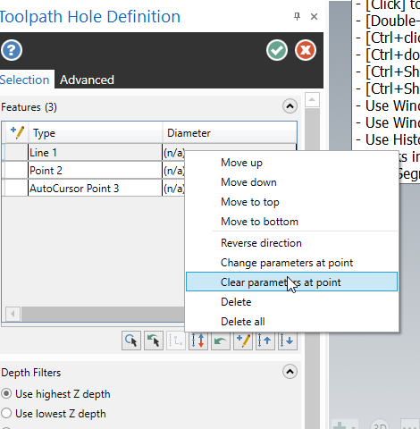
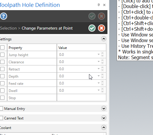
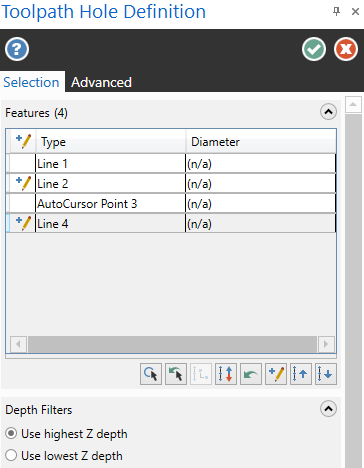
For holemaking toolpaths, this is done right from the Toolpath Hole Definition panel where you select the entities- just right click on where you want to make the change: Points that received edits will show the pencil icon in the first column:
-
A major impediment to doing so- anyone that had previously set up a specific start angle parameter would have their helix bore shift clocking if they regenerated.
-
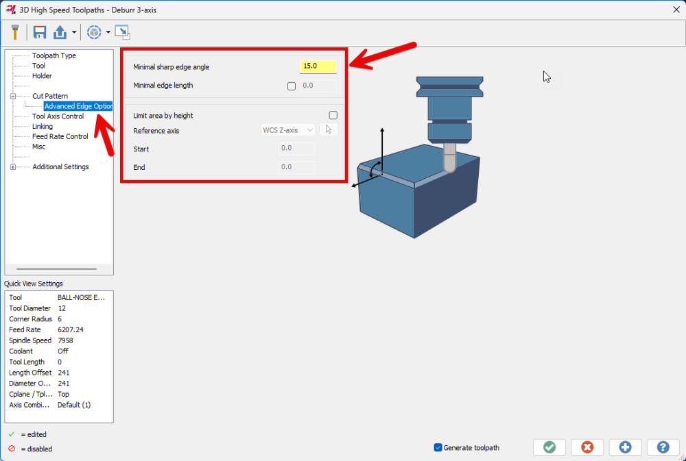
Well, Jake got to it before me and did a great job listing out some of the reasons to use Deburr rather than 2D chamfer in contour. The latter is a 2.5D wireframe take, and the former is a fully model aware toolpath with a lot of smarts built in specifically for breaking edges. Don't forget about the options on the advanced page, where you can mess with the minimum edge angle necessary for it to "Find" sharp edges to break when set to auto, along with some other controls to filter out edges under a length threshold, and to target specific Z zones:
-
It definitely is not a simple lift- If you look at the spun-off 3 Axis Deburr for 2025, this is outputting arcs and lines, not just linearized segments, so that it has a wider availability to existing/older 3 axis posts and machines. This was a large component in the development of this toolpath.
-
Yes- all arcs are linearized when using Convert to 5
-
Went to answer with this, scrolled down through the replies and found Aaron already here.....again....
-
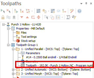
This is intentional. If you left-click on the Toolpath node of an expanded toolpath, it launches into Backplot, and if you right-click, it launches into Verify. To avoid this behavior, right-click somewhere other than this line:
-
For the Beta period there's some licensing hoops to make it available. If you want to test it, please reach out and we'll get you sorted to use it during the Beta cycle. Dan Parry, the product owner, posted about it in the official forums- you can contact him through [email protected].
-
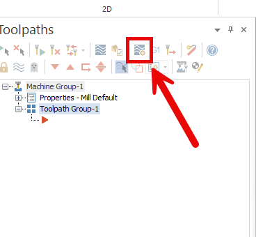
This button, starting in 2024, also takes you directly to the Simulation settings page and Stock choice in MGS, which controls both Verify and and Simulate
-
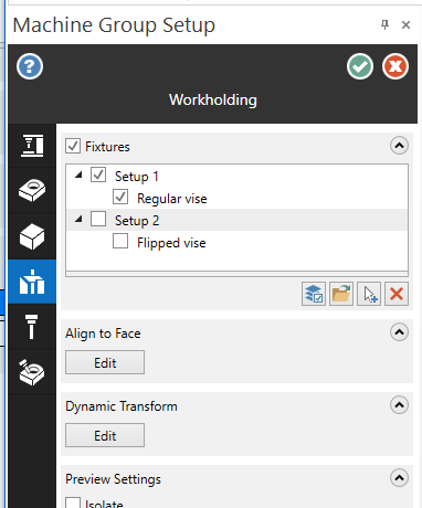
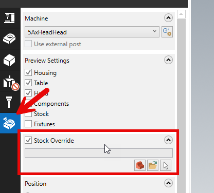
There are two things that will help retain the "one machine group, multiple setup" flow preference in the near term with new Machine Group Setup: 1. Multiple ways to override the Stock page selected stock for what you actually want to use in Simulation. In 2024 you have the "stock model operation" override talked about earlier in this thread, where selecting a stock model op as the first op in a selection to launch into simulation with will automatically apply that stock model as an override no matter what is selected elsewhere. Also in 2024 you have the Stock Override choice in the Simulation options last tab of MGS, where you can override the stock permanently and just point to a file, solid, etc. 2. In 2025, the ability to make Workholding items or Groups Active or Inactive. This means that I can do things like select a bunch of solids and group them and call them Setup 1 and Setup 2, for example, then turn off Setup 2. This has the end effect of passing only the stuff that's active (Setup 1) into verify/simulation. This way you don't have to keep on adding/deleting workholding to support a multi-setup flow- you just toggle between your organized fixture sets. This is trying to take what you used to do via level organization, (IE, stuff all of setup 1 fixturing on a single level, all of setup 2 on a single level, etc) and divorce level management of individual solids from the act of organizing and simulating groups of fixturing. These are a few immediately visible steps along the path that the team is taking to make MGS actively support and encourage single-machine-group, multi-setup flow.
-
Always fun to see what tilting towards extreme efficiency and ultimate muscle memory for a power user looks like Very early on in my career I was at a shop that handled things similarly to the "one file per op" approach. I cannot imagine being shackled by that in the year 2024!
-
This is the flow I always taught as well.
-
Yes, new to 2024! One of my favorite new features and instantly something I can't live without.
-
If you look at the Update releases, generally Mastercam has been moving from a small number of large Updates, to spreading these out over a larger number of updates which can be delivered faster. This means that, among other things, we can sync up to things like file format changes for importers for different software like Solidworks/etc closer to when those other products release, rather than waiting months and months for the next Update to drop.
-
Anyone using MasterCAM in Optics manufacturing?
Chally72 replied to Wes09's topic in Industrial Forum
^this 2024 scales 5ax path vectors to a unit vector before inserting into the NCI to avoid some of these rounding errors throughout the process, and vector mode will further reduce the possibility of fuzz/jitter. -
That "Stock Plane" should really be labeled something like "Transformation plane....don't touch this unless you have a really good reason to do so"
-
Here are two videos that go in-depth on how to utilize in-process stock models and how to set up the planes to move between Op setups, machines, vises, etc:
-
Push Pull Function opening behing Parameters page
Chally72 replied to Thee Cutterman's topic in Industrial Forum
What you're seeing is the Graphical Linking Planes added to all holemaking toolpaths in Mastercam 2024, which provide graphical push-pull planes for holemaking linking parameters. See the video below for information. The graphical plane is huge and is taking up your entire screen, which is why you get that blue tint and can't see what's going on. If you zoom out your view you'll see the plane. The plane is supposed to be sized so that it is slightly bigger than your hole size (if set to incremental) or hole set X and Y extents (if set to absolute). What is your hole selection here? Note if you don't want to interact with these planes, you can turn them off with the Graphical Elements toggle button in the top bar of the toolpath. Here's another video from the rollout:


