Chally72
-
Posts
499 -
Joined
-
Last visited
-
Days Won
32
Content Type
Profiles
Forums
Downloads
Store
eMastercam Wiki
Blogs
Gallery
Events
Everything posted by Chally72
-
Hey Husker, it looks like this one is already fixed in 2023- ref D-45601. It's related to use of the Apply button, so if you just skip using Apply in 2022 and green check out, it should allow you to avoid this for now.
-
I'd just send the questions to your reseller. CIMCO probing, when we did testing, came with the modified haas 3/4 axis post directly from them and it was 100% plug and play. I'd be very surprised if there were suddenly any issues with posted output. If your reseller used their own post and added CIMCO probing routines, (which is not a big deal to add into a post,) then maybe there are some slight tweaks to be made.
-
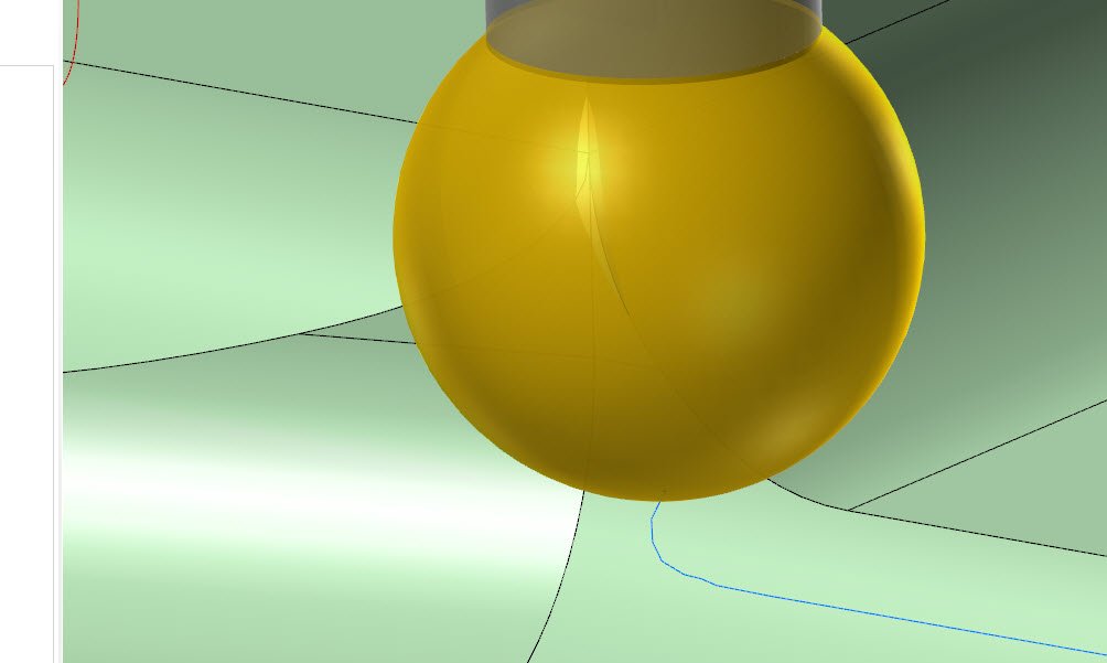
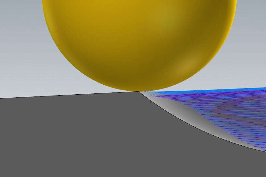
Hey Sigurd, I assume your problem here is unwanted cutting of the top surface of the part at the end of Toolpath 2 which is doing the cavity, and where we see the "Band" machined in your part picture that doesn't exist on the model. What is likely happening here is that because you are using two different tools- 0.280 ball for Path 1 and 0.311 ball for Path 2- is that you have some slight error in the tool Height offset. The way this is programmed is primed to show even the slightest height variance- Note here how Toolpath #2 takes a pass right at the sharp edge of the cavity. If those two tools are not perfect in their H offset down to the tenth of a thousandth, you'll get mismatch because you're essentially asking one path to remachine part of the other with a zero tolerance: Backplot and Verify/Simulation would never show this because of course in the computer world, all the tools are a perfect shape with perfect height offsets and no wear! To avoid this situation, you could do something like Turn on Tool contact point in the Toolpath Control page, and then also go to Model Geometry and add the Top Face and Front Faces as Avoidance surfaces to clean up the motion that Tool Contact Point creates. I think you might be using Toolpath #2 as both a roughing and finishing path, so this may not be viable, but it's how I would avoid these "accidental" remachining circumstances. Another solution would be to finish both surfaces with the same tool, if possible. This will naturally avoid this tool offset problem you're encountering.
-
 Linking would be a big one. By transforming within the operation, rather than transforming an operation as a whole, the NCI is radically different in terms of headers and how it could be read/interpreted by the post. Note also the sorting options you have to do some more intelligent things with how you break out that toolpath and do each depth on all transformed contours before moving to the next, etc, which can only exist if the transform is calculated within the toolpath itself. It's also nice in the case of blades or other repeating shapes to have all information related to cutting the part contained within one toolpath, rather than spread across two- the Morph/etc AND the transform.
 -
Just a note that the Core certification program is new and most of the materials are completely revamped in the last 12-24 months. Usefulness depends on a few factors. I've had job shops that cared more about their own practical tests, and big corporations that all but required a cert of some type.
-
If you are Saving and Loading defaults in the actual toolpath dialog, this WILL affect the point sort order in the hole selection panel as well, so you can set point to point, green check out of hole selection, and then click Save in the toolpath to overwrite your defaults. Remember that sort order, like other toolpath parameters, will also change state based on "last created op" unless you've turned that behavior off in config, so if you're creating multiple subsequent drill ops, it's always remembering what you created the last op with and then starting you off with that as a setting.
-
Hey Kendo, could you post the file or send it to me if possible so I can poke around and offer some suggestions? In the subpages under Cut Pattern, there are options for height control similar to steep/shallow, but a lot of conventional Optirough wisdom does not apply here. Looking at your part shape and approaching it with my apps engineer hat, I'd probably choose to go after this with multiple Optiroughs with stock models, but with some preconfigured settings with 3+2 auto, perhaps you can get something approaching as efficient as opti with a little less time invested.
-
Just an update that a defect was logged for Thread Mill spring passes not keeping override RPM- thank you for sending me the file.
-
Verify has gotten a lot of attention in 2023 to try and cut down on the number of issues- I used to also have to shut down/restart Mastercam quite a bit in 2021/2022 to "clear the works". A good chunk of the issues can be solved in '21/'22 by going into the Verify/Simulator options and toggling your machine selection to something else, then toggling it back to the one you want to use. The spring pass issue is something that should be looked at, if you have a file.
-
I know that in the case of things like the C axis of UMC's, when running a Next Gen Control, there are no longer any windup limits and you can safely change the control def min and max travel limits to a number of 9's in a row, (or go and edit your .pst if the axis limit values are stored there), to remove the unwind being added to your posted code. I think the limit still exists on the ST20's, however. You can give it a try and the worst that will happen is it'll reach the machine's max windup and then stop and throw an error when you hit degree 36,001.
-
Hi Rob, I sent you a message but haven't heard from you. If possible, I'd like to take a look at that toolpath so that we can determine if it's a toolpath-level issue or a rounding issue when the NCI vector is converted to an angle- (Very likely the latter and I'd like the team to look at it).
-
How to make use of Blade expert toolpath to create Morph toolpath?
Chally72 replied to Shiva.aero's topic in Industrial Forum
Hi Shiva, Here's a video showing how to build up a regular morph toolpath on an impeller to get similar motion to what you'd get in Blade Expert. Using Oval form tools, you might not use this method of From Chain, but instead set side tilt by angle or contact point in the Tool Axis Control page. Trying to get complete, clean paths using oval form tools on impeller geometry is a large programming challenge. You can always use the trick of using a path like Blade Expert as the source path for a Convert to 5 Axis operation, and take advantage of this to swap out the tool to an oval form tool from a ball mill and adjust the collision control tilt and retract. -
Hey Jake, Even though we're locking this to 3 axis, Deburr is still a multiaxis path in the background, whose output is restricted to linear segments- so there's no way to have this path type output arcs. Depending on your machine, you should try going after smoothing/tolerance parameters at the control to loosen them up and allow the machine to flow through these linear segments more naturally- IE, Haas G187, Heidenhain Cycle 32, etc. Using a looser toolpath tolerance to avoid dense clumps of points will also help. That 0.0005" tolerance on your example path inserts some pretty clustered groupings that would wreak havoc on machines with no/limited smoothing and lookahead.
-
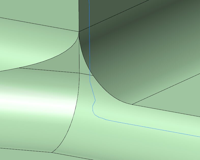
Hey Jake, thanks for uploading the file. This "noise" issue is something we spent some time addressing for 2023 to improve results. This is happening specifically in the area where those two sharp edges come together to the single edge- What happens when the lollipop transitions through that "Y" is that at some point, we need to shuffle the tool to the side so as to not violate/gouge our part beyond our allowed edge break and tolerance. 2023 handles this a lot better and gets rid of the funky oscillation. It actually helps to loosen the tolerance back up again, so as to allow more wiggle room for the tool to overcut/gouge as it reaches those intersecting surfaces. I brought it up to 0.002" on your path and regenerated. The remaining zig you see below is the minimum necessary move to avoid chewing up the adjacent edge as we pass through the Y intersection: And here's what it looks like for tool engagement in backplot:

-
Cutter Comp Beginning on Arc Move - How to Avoid?
Chally72 replied to Bill H's topic in Industrial Forum
There are a few things we're looking to do to alleviate these issues in the future: -Change helix mill entry/exit sweep default to 90°. Because of the math being used to automatically create the lead arcs, 180 degree arc sweep and control/wear comp immediately put you into the scenario of turning on comp on an arc- and invalidate the use of Start/End at Center to get you that linear move. -Notify a user at toolpath generation that cutter comp is being activated/deactivated on an arc move, and suggest adding a linear entry/exit. This would replace the need to add this logic to the post just to see the issue that is being created at the toolpath level. -Make it easier to add perpendicular entry/exit in a relevant way. -
I'd want to take a look at the file before answering that one, so as to attempt to give correct info! Please send it over if possible, or perhaps email pictures if not.
-
Deburring with the top half of the lollipop in restricted axis scenarios has been especially challenging to get right. There have been some improvements in 2023 for these scenarios- If you can upload the file or send it to me, I can see how we're handling this now and if further improvements can be done for your scenario.
-
The size is too big to attach here, but it can also be saved/viewed as a PDF once installed. I'm not sure why the PDF isn't available individually for the Beta
-
It changes what is considered a corner to apply this roll to. By setting it to All and then considering the 3D spline and trying to find/apply rolling to parts of the profile that might be considered corners, it was incorrectly applying arc motion to segments of those part corners. I'd expect it to have some trouble in scenarios like this, especially depending on where the model came from/what the shape of the spline was.
-
I took a look at the file. Having Roll cutter around corners set to ALL on the cut pattern page and having it enact changes upon the 3D splined edge at the corners of the part was inserting small arc segments that were causing this up and down noise. Setting it to Sharp or None drops it away without having to modify the tolerance!
-
If you can, please send me the part file so I can take a look.
-
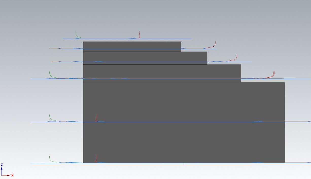
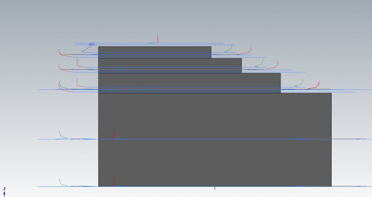
Without getting into application specific examples, the problem you get into as a user, especially when you start adding in Floor and Wall Stock-to-leave values on the Geometries page in Opti, is extraneous passes when really you might have just wanted to do full stepdowns and then come back up and hit all flats. IE, here are results when I have requested 0.05 floor stock-on, on this pyramid step part with vertical walls. Let's start first with a 0.5" stepdown, 0.0375" step up: Because of the way that the Stock-to-leave values are taken and the original model is "puffed", I get extraneous passes around each step that I technically didn't need with my part geometry. Now, I take the same path, and set my Step up to be equal to my step down, and I get this, which is closer to what I expected: No extraneous passes, I hit all my flats, and I respect my floor stock-on values. Now, get into a mold cavity or something with a draft that requires step-up values, and you can't avoid Scenario #1, because yes, your bigger concern is getting the shape to near-net with your roughing, and setting step-up equal to step-down is no longer an option.


-
At the risk of oversimplifying, if you wanted to hit every flat and just the flats, and have no extraneous cuts, stepdown=stepup would be the way to approach it.
-
This is one of those "Hey did you know" things I have to throw in to every training lesson on Opti, because it's not explicitly spelled out in the interface that "doing X allows Y."
-
That's correct!