


Chally72
-
Posts
499 -
Joined
-
Last visited
-
Days Won
32
Content Type
Profiles
Forums
Downloads
Store
eMastercam Wiki
Blogs
Gallery
Events
Everything posted by Chally72
-
That's unfortunate, as embedded videos worked really well here.
-
I made an extensive video on plane linking and associativity. Give me a day or two and I can link it here- for some reason it isn't up on our Youtube right now.
-
Can you send me the file? [email protected] If you ever right-clicked on a plane in Mastercam 2021 and earlier and hit Create Relative as a method to create new custom planes, those planes were linked in the background, though we didn't have an icon to tell you that in the past. If you generated a Report on the plane (right-click, Report) you'd be able to see the interdependencies. The Link symbol appearing when you bring it into 2023 suggests that they were indeed tied together, and perhaps the Lock is not being applied at the right point in the process when you migrate the file into 2023 and it tries to figure out all the associations and interdependency rules.
-
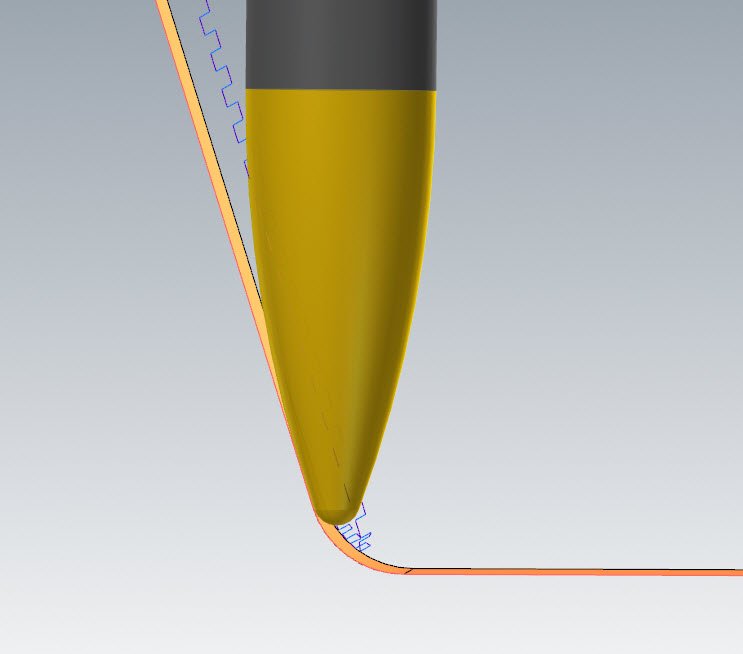
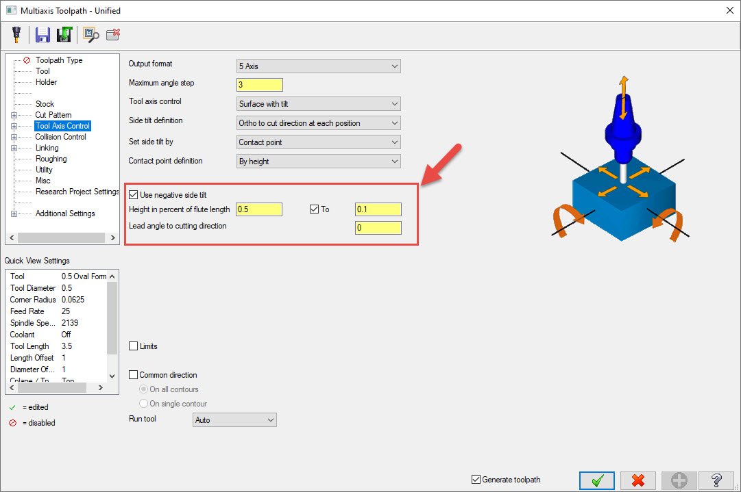
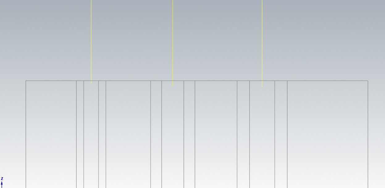
There are a few ways to get after this. I attached an example file. Toolpath 1 is just to show our starting point and what we have to solve. We have a side profile that we need to cut down to the fillet, but starting off with a cut pattern that contacts in the middle of the Oval form profile, we can see how far past our "floor" it would have to travel to respect where we want to start the oval form cut. So, this is what we will attempt to mitigate in the next steps. Toolpath 2 shows a very simple change- Rather than setting up our floor and fillet with a Trim strategy in collision control, set them to a Tilt to avoid strategy. This will maintain the same contact point on the oval form tool until we start to get into the interference area, and then it will tip the tool farther and farther onto the nose in the last few passes to clean the surface up. Don't be afraid of the blue path lines doubling back on themselves here- remember that they represent the tip position of the tool, and NOT the actual contact position of the tool flute against the surface- which still maintains its nice even parallel spacing. Toolpath 3 shows a way to feather in this nose tip tilt over the entire path- turn on the TO field in Tool axis control and it will tell the path to enact a gradual FROM/TO contact point change over the course of the entire path. The value in this box is a 0 to 1 value that corresponds to 0 to 100% length of the flute, as an approximate desired contact point. So in this case, I start off at the top of the wall with my oval form cutting roughly in the center of the profile, and feather the contact point towards the tip over the length of the path, so by the time it reaches the floor fillet, the Tilt to Avoid strategy doesn't really have to do any adjusting, because I've already removed the gouge while mostly maintaining the benefits of a big stepdown with small cusp that Oval forms give me. This method will also make it harder to pick out a visual discrepancy in surface finish from rapid angle changes or rapid effective cusp width changes that would occur when we suddenly start adding large tilt to the path like we do in Toolpath 2. Example of Oval tilt.mcam

-
 Hey Tom, could you PM me a file on this one? I'd like to explore.
 -
Here's one on Advanced Drill: https://youtu.be/TgHTs6Ol3W8 And here's the part file used in the video: https://community.mastercam.com/TechExchange/Parts/782#partTitle Also, we made a nice video on Chamfer Drill which I completely forgot about. 2020 was so long ago.... https://youtu.be/akWH7szYdAM And here's another one using chamfer drill in a mass hole scenario: https://www.youtube.com/watch?v=xRx6T4CaFV8 Because Advanced Drill and Chamfer Drill are not cycle-based, they have the advantage of extremely reliable, dirt-simple output that will perform the same on basically any machine with any post. This does make them less "readable" at the control, or less accepting of hand edits, but these paths do things that cycle based output simply cannot do. And yes Ron, if you have an uneven breakthrough and have to actually contour chamfer rather than spot chamfer, you have to fall back to exactly what you mentioned. Breakthrough treatments are a future area of opportunity to offer easier/more intuitive path creation options...
-
Just a note that Zero is a valid size for chamfers in Chamfer Drill, so you don't have to use Ron's method to get the physical chamfers you want. Different chamfer on each hole? Model them all in. Same chamfer on different holes? You don't have to model them in to get what you need. Chamfer drill was designed for these scenarios- to allow a single op to tag all sorts of different modeled chamfers, or to allow you to specify a chamfer size if the chamfers weren't modeled in. The spotting method is kind of a hijacking of it since you aren't technically producing a Chamfer, but I use it all the time to condense my spotting operations when I don't have to get too picky with spot size across a range of diameters.
-
Radical, do you mean the Preview toolpath button that used to live on the top toolbar of a toolpath dialog? That's been merged with the Apply button (Blue Plus) next to the green check and red X. So, Apply is really now "Apply and Preview" in 2023. Yes, this is super unclear and I hope we can make this more distinct in the future. Hope that helps!
-
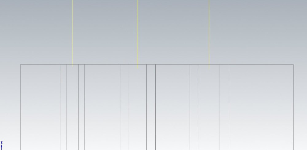
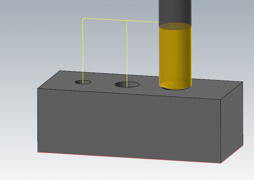
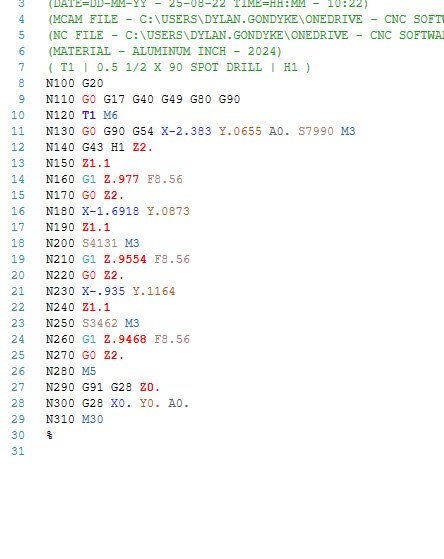
Check out the attached sample file- 3 different hole sizes, all spotted using a 142° tool in a single toolpath. Here you see the different depths we drive to on each size: On the three different holes: And because we checked "Maintain SFM", we get spindle speed drops as we go up in hole size: Sample Spotting.mcam
-
Have any of you played with the Chamfer Drill toolpath to do spotting on dissimilar holes or groups of holes? This will allow you to enter a positive or negative number for chamfer depth, and automatically adjusts SFM for different hole sizes. So if I wanted to do something like spot 4 holes of 4 different diameters to a spotting diameter of (Ø - 0.020"), you could do this with chamfer drill and have variable depths on variable hole sizes, with variable speeds, all in a single operation.
-
Unfortunately not, but you shouldn't have too long to wait to see the update with this change.
-
Hey Tinger, I'm told that it's being changed back to the larger character limit in a 2023 Update. It's a character limit in Machine Group Setup, not in the Control Def.
-
Hey Tom, I see this and I can't see any way to swap back to the custom geometry. I logged this as R-31973 for the sim team to take a look.
-
This is one possibility, Glenn. There are also now some nice quality of life things we can do with this when bulk-adding points through Ctrl+click or window select regardless of sorting method. Point to point with a user-defined start point is not going away. Any enhancements would stand alongside it.
-
Yep, this is a known issue with 2023- it will do a minimum distance sort and ignore your start point and use the optimal start point. We're looking to get this fixed in an update. It will not be in Update 1.
-
This parameter is not exposed in MW paths- There is a request open for this ability- R-25392
-
Hey Tom, I couldn't get this to work for me, either. I logged this as R-31608
-
The "move" you see on the screen while in the command is, to my understanding, a lightweight graphical preview. When you actually click the green check to accept is when it goes through and moves/copies the full entity selection. For massive selection sets, this can mean that you appear to see the "move" disappear for a bit and then reappear when it finishes up. Is it not ever moving the elements upon green check now? Did you set it to place them on a specific level on the Advanced tab, and that level is currently hidden?
-
Imported Mesh "Non-manifold and/or not watertight error
Chally72 replied to CNCZACK's topic in Industrial Forum
These are all using the mesh directly in toolpath creation- there are no surfaces in the above images- only meshes. There is no surface created from the mesh, nor is this possible within standalone Mastercam. Packages like Verisurf are where you start seeing mesh to surface / mesh to solid capabilities. Your success in using meshes in your application will be highly dependent on how your raw scans come in and what you're using to generate the scans. Are they clean enough that you can perform a little housekeeping and then proceed with using them, or are they messy, with flyer facets and topology issues making up a large portion of the data? -
From when I've done similar in the past- the post has to be specifically set up to do this. The secondary vector (XY clocking) of the toolplane is in most cases not considered, and here you need it to be respected to get the correct output.
-
Imported Mesh "Non-manifold and/or not watertight error
Chally72 replied to CNCZACK's topic in Industrial Forum
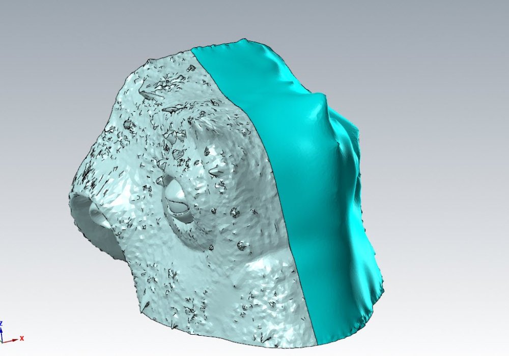
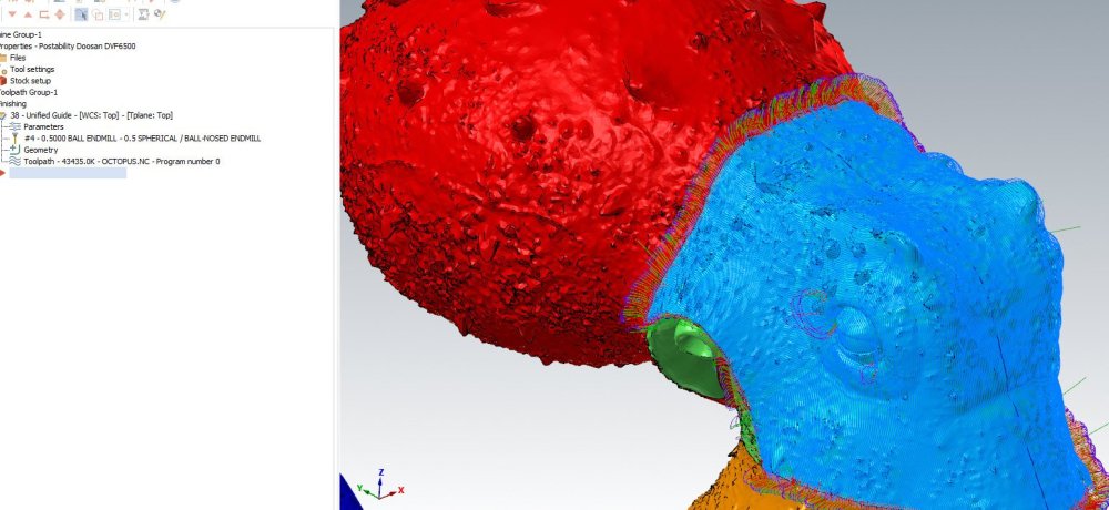
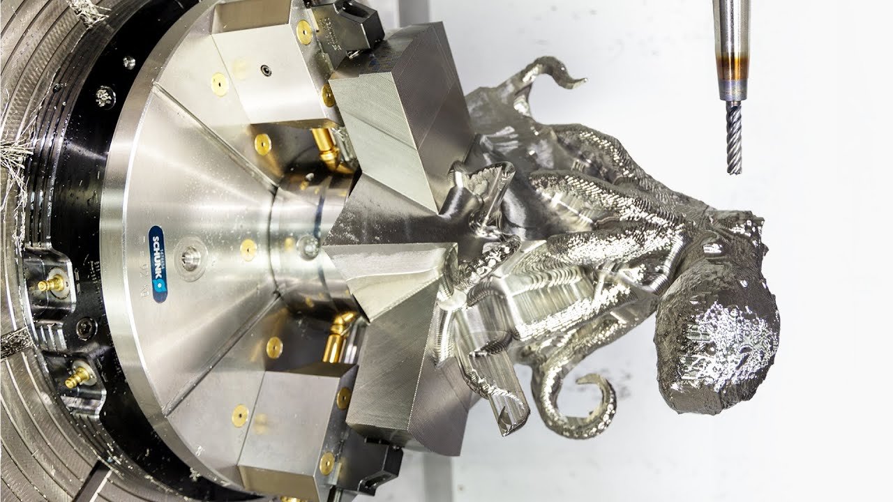
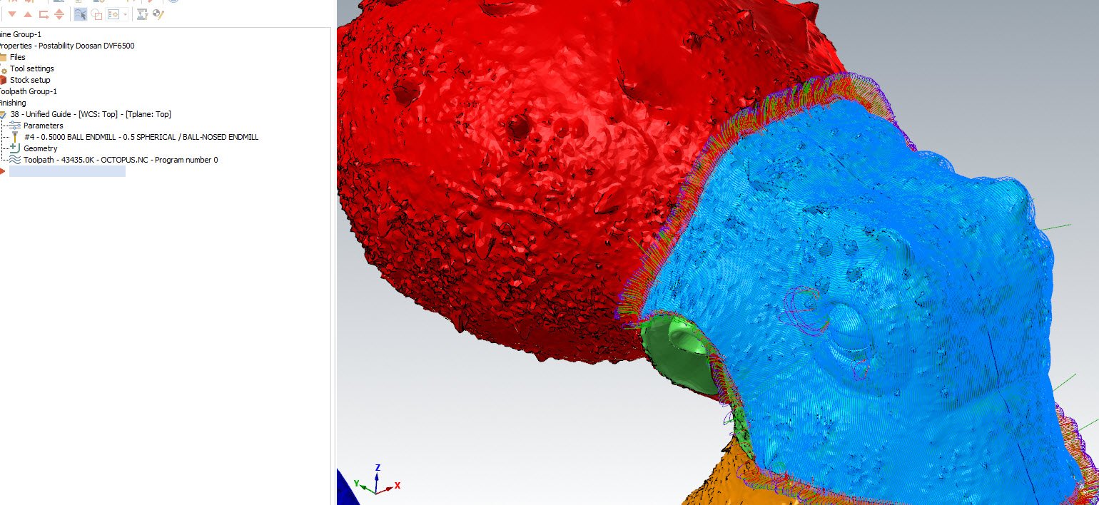
If the end goal doesn't involve creating a solid or trying to mimic/get back to prismatic shapes, the mesh tools within Mastercam are some of the more advanced I've used outside of a dedicated package. The Titans of CNC Octopus is one public example- a single large (1 million polygon) mesh file taken through the entire machining process without the need to create a solid: Using the mesh smoothing commands to create "clean core" entities to drive the tool vector control over the crenellations of the octopus scan, while still using the original mesh to drive the tool linear position: Using Smooth and Refine to boost polygon count in areas of low resolution and to clean up the shape, like the eye:
.thumb.jpg.9a6959fb198addeaff6225489c4ffc65.jpg)
.thumb.jpg.1e7596e2b0ab52b3b62e12544bfee402.jpg)
-
Imported Mesh "Non-manifold and/or not watertight error
Chally72 replied to CNCZACK's topic in Industrial Forum
The mesh will need to be checked and cleaned up before you can use any of the more advanced mesh commands. Use the Check Mesh tool to analyze the mesh and view where errors are. With a raw scan, you probably have a LOT of errors, overlapping facets, etc, that need to be cleaned up. In 2023, Check Mesh will also allow you to delete the problem facets. With 2022, you'll have to manually clean up any problem facets. You can use meshes in a fair few areas of the software, including toolpaths, so don't give up and resign yourself to only considering solids. If you search for "Mesh" on the Mastercam youtube page, there are quite a few videos showing how to clean, trim, and manipulate meshes. -
We found the trigger for this- it's logged as R-31531 and the team is looking into it.
-
Missing End Selection & Clear Selection buttons
Chally72 replied to R-Miller's topic in Industrial Forum
Hi R-Miller, This was a particularly difficult one to track down, but we did find and fix this in 2023. The trigger seems to be when switching selection types between curves and surfaces in toolpaths that allow you to do so in some manner. In certain cases, simply reentering the selection step a second time will allow the buttons to reappear, and in others, you'll have to close and reopen Mastercam. -
If Jamie works for CIMCO too, his current team is going to be quite shocked. ;) The CIMCO arc creation issue should be sent in to CIMCO for investigation. The red line issue- that's all Jamie. (and me)


.jpg.8850f350113c64b41f9166181678ec15.jpg)
.jpg.f25371be6feda3dba5cfa7c9897e2b3b.jpg)
