All Activity
- Past hour
-
 pacinozheng joined the community
 -

Does MCAM allow parametric drawings/models?
cncappsjames replied to Tinger's topic in Industrial Forum
A LOT of years I did ALL my CAD in Mastercam. It's VERY good at the part level for CAD... minus not being parametric. However, there came a point around 2006 or so IIRC where it became just too much because certain projects I was working on were changing too frequently so then I got into CATIA. Around 2015/2016-ish I migrated to Autodesk Inventor for nearly all my CAD needs. From time to time, I will draw a part in Mastercam... because I can , and sometimes certain features that I cannot figure out how to build in Inventor, I'll build in Mastercam... again... because I CAN. You could drive CAD from a spreadsheet. I was awesome. I did a BUNCH of lathe family of parts projects with it. I was REALLY sad they abandoned it. I KNEW it would be hard though. -
Possibly flowline is a better option but without a file to look at it is just a guess.
- Yesterday
-

C-axis Face contour won't work with y axis
heavychevy2155 replied to Jese's topic in Industrial Forum
May want to use reverse wear comp. -
Parametric is wonderful....
-
I have tried to push for it,.. but we are not. New "big" customer, they want a small family of parts, supposedly around half a mil per year of work so we are doing it on the house. Makes no sense to me but I'm just a measly paid-by-the-hour programmer.
-

Does MCAM allow parametric drawings/models?
Aaron Eberhard replied to Tinger's topic in Industrial Forum
Right, which is I don't consider the wireframe stuff as parametric -
Simplest I understand what you're going for it however, it doesn't truly align with what is a "Parametric" modeling CAD system. Mastercam is an Etch-a-Sketch compared to a parametric CAD system. It is functional, it does work. You can do some pretty trick things with it....it does however take a lot more to get stuff done I certainly hope your front office is quoting that NRE for that work
-
Lately we have had a few customers (even a big aerospace one) give us only .PDF prints and no CAD files whatsoever. Has been a bit annoying having to draw and extrude these parts lately, as I am not super experienced so it can take me over a whole day just to draw up and model a part LOL. I mean, it all pays the same, but it's annoying and it opens the door for me to mess it up even easier haha. Not to mention it's just time I should be spending doing something more important, and I know we do not charge for this process, we just eat the cost.. When the print has CLEARLY got 3d views of a modeled part but the customer swears up and down they don't have access and can't get a solid file... anyways rant over, and apologies. I will sometimes use multiple machine groups in the same .mcam file, one for soft jaws/fixturing op and then the op2/whatever. It is a big can of worms that I know we have all discussed before but when doing "parametric fixturing" it really comes in handy. I will program the op2 before the fixturing, so I can manually move around the soft jaw wireframe and regen the soft jaw solid. Or adjust a large chamfer on a fixture to accommodate a certain toolholder/whatever situation I encounter while programming. Amateur-tip: when creating your own solids for parts/fixtures I definitely recommend notating each extrusion/boolean/whatever for when you want to go back and make changes. I'm currently working on a part for the MAM which the customer of course did not supply a solid for, so I had to create one. Nice and clear notations I also have the baseplate, which bolts to the pallet, and the subplate, which of course locates and mounts to baseplate, modeled up and labeled as well. And for each nut/bolt/dowel pin, it's got the description as well as the mcmaster part number.
-
 Konstantin Aginskiy joined the community
 -
 bclark222 joined the community
 -
Does MCAM allow parametric drawings/models?
Aaron Eberhard replied to Tinger's topic in Industrial Forum
In its truest sense, Parametric just literally means "driven by parameters." Pragmatically, that means that there's a way to alter the parameters and regenerate the model based on the edited values. You can expand that to whatever degree you want, but whether the parameters making it are generated by manually adjusting a dimensions or by a formula or by referencing a spreadsheet, the result is the same. This is why Solids in Mastercam is parametric (edit the base wireframe and the solid will update) and the wireframe is not (there's no parameters that will cause wireframe to automagically adjust). Mastercam can absolutely do the same thing as SolidEdge, when you extrude a solid, there's an option on the advanced page to create it without history. From there you can use push/pull, move, etc. There's various stages to what they mean (half the time they don't know ).... Parametric CAM can mean something like Mastercam (update the solid/wireframe and the toolpath will update) all the way up to generating toolpaths based solely on an input formula. -
I've seen people mentioning Parametric CAM. Not sure what that means though. Does that just mean the solid has a feature tree?
-
 TD-S joined the community
 -
You can use spreadsheets to drive different configurations of parts, you can use formulas to dimensions, you can define a single dimension as a variable and then tie many things to that single variable.... The Push/Pull in Mastercam is akin to utilizing a blow torch and butter knife...yes, it works but it is a rudimentary tool.. One of my guys was timid over bringing on Solidworks for our design work...now that he's up to speed on it, he wouldn't go back.
-
I find cutter comp on an arc move is pretty suspect at the best of times. Even when it's just wear.
-
 FernandoJ joined the community
 -
 FRIDANT joined the community
 -
Here's a quick and dirty example (ignore speeds/feeds/doc) showing how multi-start and lead works. This example only works with a proper form insert (3tpi acme insert in this case), otherwise use custom thread as Craig suggested. 3 threads per inch with 3 starts effectively turns the lead into 1 thread per inch. Everything in the cycle is set for a 3tpi acme thread, save for Lead (in "thread shape parameters") and Multi Start. Lead needs to change from 3 to 1 because 3tpi/3starts=1 thread per inch per lead. Next, check the Multi Start option in "thread cut parameters", select the Multi Start button and enter your number of thread starts. Because of how the tool will offset the amount of lead given for each start, your start position or acceleration clearance must be adjusted accordingly. ACME 3TPI Multi Start.mcam
-
Neither equal scallop or regular scallop seem to adjust the stepover based on the angle/shape of the surface. They keep the same stepover/down regardless. Am I not checking a box somewhere or is there a finish toolpath that looks at your max scallop height and can increase or decrease the stepover based on geometry? I only have access to mill 3d, not the multiaxis paths.
-
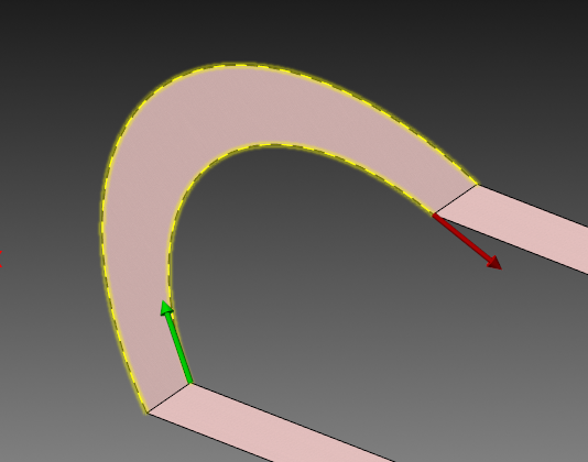
Thanks! I had never used Reflow UV before and I was trying to reflow all three surfaces together, rather than just the one....of course in hindsight, it makes sense to just do the one. I've also used "single row only" in flowline, as I never knew what the purpose was. Turns out checking single row only and setting to spiral effectively blends the three surfaces together, cool! Lastly, when I was trying Blend, I was chaining the curves along the surface and getting lift at the 45*. When chaining a projected flat curve, no more lift...interesting! I have even less experience using Blend as I do drawing surfaces, so I'm still figuring out how to chain the curves and set the Projection settings, both in toolpath control and cut parameters.
-
Does MCAM allow parametric drawings/models?
SuperHoneyBadger replied to Tinger's topic in Industrial Forum
I came up with SolidEdge and their "Synchronous" (insert trumpet fanfare) modelling. So the way I learned was the wireframe makes the initial solid, then, in MasterCam terms, you delete the wires and use the Push/Pull arrow, or Move to change a face/dimension. I never even thought to change the wireframe to resize a solid, as I immediately blow up the solid history. I have always really enjoyed making solids in MasterCam - as I progress, I do yearn for some associativity from time to time - but hey, this is CAM. Also, from my understanding talking to a few SolidWorks guys "parametric" they use referring to some form of spreadsheet or table that can drive geometry with formulas and such? Am I off base with that? -
Does MCAM allow parametric drawings/models?
Aaron Eberhard replied to Tinger's topic in Industrial Forum
Solids will be parametric if you make them in Mastercam, but the 2d/Wireframe part of it is not, which is very confusing to people who have only ever drawn in sketch-based software like SolidWorks... But it's just the way CAD was in the 80s For example: You make a wireframe rectangle that's 2"x1". You cannot create dimensions that you can edit after the fact and both sides of the rectangle will go to 3" instead of 2". You have to move the right side line, then extend the two 2" lines. The closest thing to doing this easily is Transform > Stretch, but it's not nearly the same as Solidworks/Inventor/etc. just editing the dimension. You have a solid that's been extruded from that 2"x1" rectangle. After manually manipulating the wireframe to extend it to 3"x1", the solid will be regenerated at the new size, so that is parametric. Really? That's an interesting project. I can see how that'd be dang-near impossible for a 3rd party to do.. It would take a massive rework to do it from the inside.. -
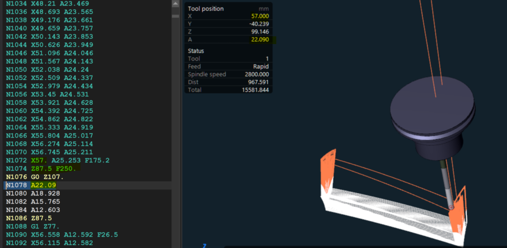
hI I am using cimco edit 2023 and i notice a new tool position display. the problem is i am running a 4 axis program with no motion along Y axis. it must be always at 0. i only have correct position for x axis and A axis .Y and Z value dont match the program positions. is it possible to modify tool position display according to program origin? and have correct tool position ? Thanks for you help
-
Mastercam Single Surface Machining and Overflow UV | Mastercam 2022 Signature Parts (youtube.com)
-
 Kristopher Jameer joined the community
 -
Have you tried custom thread?
-
 jeffkd411 joined the community
 -
 I am experiencing the same issue
 -
marthaweinstein joined the community
-
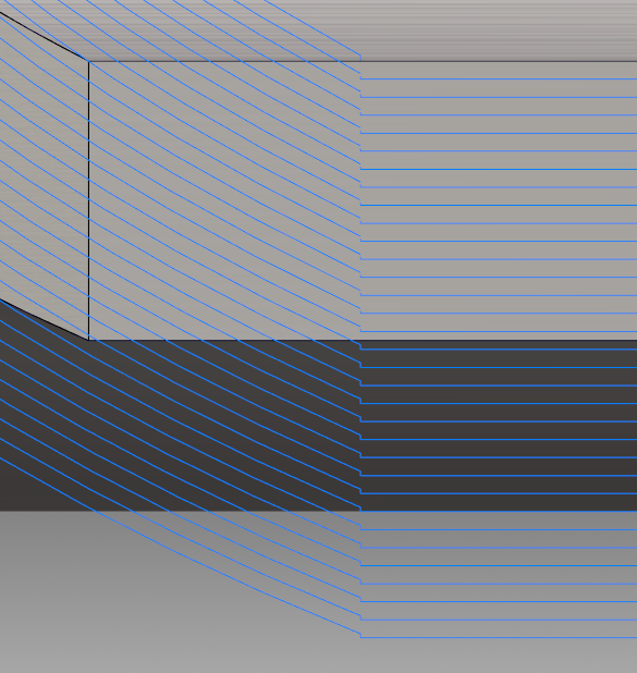
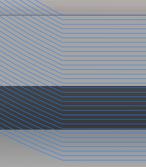
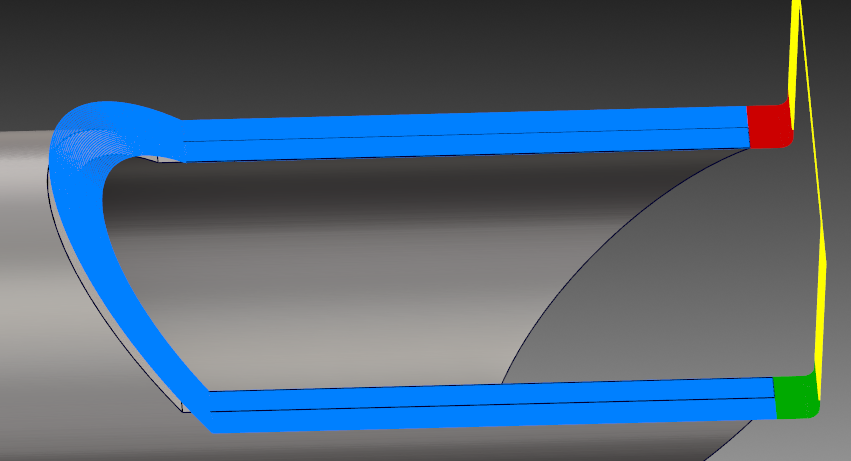
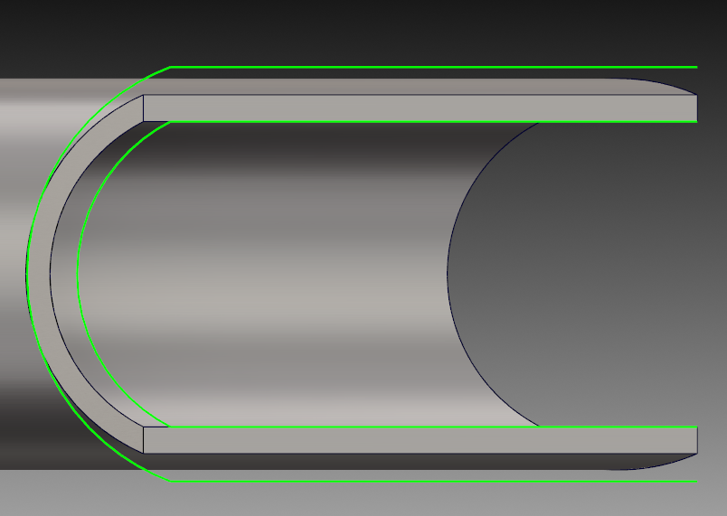
Maybe using Blend is better than Flowline, but the curve needs to be calculated... Flowline Blend
-
Sorry I don’t speak English...


-
Does MCAM allow parametric drawings/models?
cncappsjames replied to Tinger's topic in Industrial Forum
In V8 it did. MoldPlus abandoned the project though and it never made it out of Beta. - Last week
-
Very cool, thank you so much. Before coming to the forum about this, I tried using Net but I kept getting a continuity error. Turns out I was chaining it wrong, most notably with the across curves. I chained the surface without making a radius, just to see what it would do and it gave me a continuity error, but still created the surface and it didn't look warped. I opted to use a radius as you did though, as I'd rather not get any errors at all. Cool trick, same with the draft example you showed me before with turning it into a spline. I really appreciate your help. Also for what it's worth, I was able to get fairly close to my desired motion with 3d blend, but as it came down the 45* wall it wanted to lift in some areas and plunge into the stock and with the angular lead-in/out control being limited, I could only avoid the plunge by giving it a combination of horizontal and big vertical lead-in. I also had to manipulate geometry a fair bit. This net surface with flowline is clean and simple. Thanks again.