Leaderboard


Popular Content
Showing content with the highest reputation on 05/04/2020 in all areas
-
One thing you should note: The "display" of Surface Normals is 'disabled' by default. Go to the 'View Tab'. Enable the button that says "Backside". This shows you the 'back side' of the Surface, in a light-green color.2 points
-
You have a surface normal issue..... Click on Surfaces >> Change , the arrow is pointing inward, you want it the other way... I looked quickly at toolpath 13 and the exit move corrected You want this to be like this2 points
-
We all run into this...strip out everything but just the related surfaces...1 point
-
File so someone can evaluate?1 point
-
I will try but it is almost impossible to reproduce. Its so random, and sometimes when u move it back it will stay after that. I know I'm not the only one I have checked the official and quite a few people have taken notice. Is this the first you have heard of it?1 point
-
I just finished a big project in MC2021 5 axis (3+2) 400+ operations 35+ planes I experienced zero problems with tool planes, but I don't recall ever having problems in MC2020 either1 point
-
Thank You as always Colin, but sadly I have never used the duplicate plane function. I almost always use dynamic, from solid face, or from geometry or from gview. We still program from center of rotation (I know, I know) My work flow for 5 axis is almost always the same for setting up a part. I create an origin point, then make all my planes associative to that point. Reason some of the machines are different and to move machines I can move the point and regenerate with very little work in most cases.. But In 2020 plane association is broken. If I use a dynamic plane to the point I get no associative check box to work with. Only planes by solid face, or geometry will give me the associative check box, then I use the lil arrow in the plane manager to select my origin point and viola! I have the plane I need, associative to a point! But at any given time with out rhyme or reason it will just move. I have tried locking the planes which does not seem to help... Its all buggy as heck. The rumor is they have fixed this in 2021, fingers crossed, but It needs to be fixed in 2020 as well. We will no doubt not move to 2021 for at least 6 months after release, and what about the customers that do not pay maintenance or have vericut. They will be stuck with broken 2020 for life. The cost of master cam in my mind dictates the fact that no version should be abandoned for the next version. They need to at least fix the major issues and make a version stable. Honestly I am like a kid at Christmas every year when a new version is released, I love the new features and new toolpaths etc. I look forward to it all year. But I really get frustrated with how CNC will abandon older releases that are not at the very least stable....1 point
-
Hi Pete, What functions are you using to create your Planes? I ask because I have seen issues when using the "Duplicate" Plane command. This seems to "link" the new plane, back to the original plane, somewhere in the background. If you end up moving the origin of one of the planes, then the other moves as well. This has bit me a couple times. The solution I've found is to never use "Duplicate" from the Right-Click, or any other menu option. Instead, I use the "Create Relative" Function. Even if I want a "New Top Plane", the "Create Relative" Plane command can be used to create any of the "6 relative views", in orientation, relative to the "Plane you have 'selected' in the Planes Manager". This means, if I click on the "System Right Plane", and use "Create Relative", then the " Top view " in the Relative Planes Dialog box, is actually a "duplicate plane". This is true, no matter which Plane you are using the command on. Again, the "Top Plane", in the 'Create Relative' dialog, is always a 'duplicate plane' of whatever Plane you have selected in the Planes Manager. I do this because creating new planes with this function gives you independent planes, that are not associated back to the 'parent plane' in any way. You can move, rotate, or otherwise manipulate this newly created plane, without it screwing up anything else... Also, this gives me a great way to create "Front, Right, Left, or Back" views, of whatever Plane I want to manipulate. It is kind of funny, because you'd think a "relative plane" (Create Relative - Plane Command - under the "+" button in the Planes Manager), would mean it is "connected" in some way, but I have found the opposite to be true. Both "Rotate Incremental" and "Duplicate" (Plane Commands - from Right-Click Menu in Planes dialog), have given me issues. By 'issues', I mean there is some kind of weird link back to other existing planes, and it has caused my toolpaths to "jump around", due to some plane data being modified that I wasn't expected to happen. For those reasons, I've just changed my work habits to use either: [ Planes (panel), "+" button, "Dynamic..." ], or [ Planes (panel), Right-Click in white panel area, "Create relative..." ]. With 'Create relative...', I'm usually making a copy of an existing Plane (multiple work offsets anyone?), or truly creating a "Front" or "Right" plane that is relative to an existing Plane, for constructing 3D geometry. The other option I'll choose is "Dynamic Planes". I do this if I want to "create a 'rotated' Plane, relative to an existing Plane. For example, if I have a part "off in space", then I'll typically create the first "OP 10 Plane", relative to the part "in space". Once I've finished that 1st OP (OP 10), I need to create a new Plane which is "rotated 180 degrees" from the OP10 Plane. First, I'll make the OP 10 Plane, the Active WCS, Tplane, and Cplane. I do this prior to activating the "Dynamic Plane" option in the Planes Manager. By setting the 'active plane' to my current WCS, when I launch Dynamic Plane, the Dynamic Gnomon is "pre-oriented". I will first begin by selecting the point where the WCS Origin will be. Once the origin has been selected, I'll activate one of the 'rotary handles', which allow me to rotate the plane. Depending on your settings, it will usually have a 5-degree increment that will "lock" to each position. I'll make my 180 degree rotation, and then save that as my OP 20 Plane. This process can be repeated, ad infinitum, to create new Planes which are 'relative to an existing Plane', but then manipulated in some way. I'm typically "creating a new 'rotated' copy of an existing Plane" (with Dynamic...) I hope that helps... -Colin1 point
-
FANUC really does itself a disservice honestly. When I took a class in Chicago last year at their US HQ, I told 'em as much. They don't do a good job of educating those that support it's product, they don't do a good job of educating end users. THe only thing they do a good job of is making the most robust motion control product on the market. That must be enough for them I guess. So, it's up to folks like me that have a pretty good handle on them (and believe me I still feel like I'm only scratching the surface on what's possible with them) to pass along what we know so we can stop the disinformation fest the Heidenhein and Siemens fans continue to perpetrate. JM2CFWIW YMMV1 point
-
We all got to do our part to help. Everyone of us uses it differently and the most people reporting issues and sharing their user experience the better data is collected to narrow down issues. The developers don't have an easy job and for the most part it is a thankless job at best, but someone has to do it and they do their best making Mastercam do what it does.1 point
-
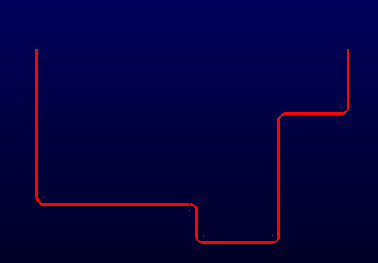
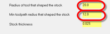
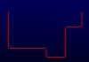
Glad you like it, Kevin! You should use both options... The idea is that this toolpath doesn't really "look" at stock remaining from another toolpath (like a rest machining/optirest toolpath would), so you have to tell it what you did previously. Technically, you only need to define the stock thickness remaining, and it'll calculate a toolpath based on that (as if the chain is "offset"), but of course you won't know if there's one area with more stock remaining from roughing with a big tool, it would just treat the whole thing you're cutting as a set thickness. So if you had a shape like this one: I have fillet radius of 5mm set in each corner, and I'm finishing with a 5mm mill. If I had roughed that out, I would use a tool with a diameter of, say, 20mm, and I may tell the the roughing toolpath to have a minimum arc radius of 12mm. I need to tell Dynamic Contour that so it can properly calculate where material is left and how to attack it:

 1 point
 -
quote: Also, I would "really" suggest using at least a bullnose to cut that. As John said you REALLY SHOULD use a bullnose cutter. Even if only a .01 rad, Flat sharp tools have always been a "nono" with 3d work. PEACE1 point
-
Motorcity, Do you want the tool to just start and exit off the part or do you want each pass to overlap the edges of the surface by more than half the endmill. You can use direction as CNC Apps said to create a lead in and lead out at the start and end of the toolpath. To get the tool to overlap the surface on each pass either extend the surface as John suggested or go into you gap settings and under tangential line length put in a positive value . The tool will overlap the surface by that amount on each pass. Just make sure it is not going to gouge any other surface. By the looks of your part you should be ok. Also the answer to you question is yes you should still get the correct geometry with a sharp cornered endmill but your step over will have to be very small to get any type of good finish. You might want to consider doing two toolpaths. The first flowline using a bullnose to do the entire surface and the second flowline using a flat endmill with a depth limmit just to take out the radius left by the bullnose. Its hard to say for sure without trying out the toolpaths. Mess around with different settings until it looks good in verify.1 point
-
For 8 out of 10 parts: rough using Surface Rough Pocket finish using Surface Finish Contour w/ shallow enabled For the 9th part: finish with Parallel For #10 of 10: finish using any and perhaps all available toolpaths. Whatever it takes to get the job done. In all cases, the cut and filter tolerances are critical to getting good results and maximizing what your machine can do. This is way oversimplified but it might get a total newbie pointed in the right direction. Good luck1 point
-
There's quite a few of us in that position here, actually. We also have a decent few who worked at OEMs, which I also was.. I was a combo I worked for Centroid (http://centroidperformanceracing.com/), we made machines to do cylinder head & block work, and we used Mastercam to do our programming. Yeah, you can ignore a lot of warnings before your engine blows up0 points