Leaderboard


Popular Content
Showing content with the highest reputation on 12/10/2021 in all areas
-
You have to make sure that the distance from the top of stock to depth is evenly divisible by the pitch. I usually tweak the top of stock a bit to get get clean code.3 points
-
Tool Management has always been an issue. We've come a long way in that department, however there is a great deal which still needs to be done. I typically do what Ron does, and I create a whole separate Mastercam File, to build my Tool Assembly in. This allows me to save that Tool, Holder, and Tool Assembly to my Tool Library, and have access to the original Mastercam File where I built that Tool Assembly to begin with. I also don't have to remember > "what Mastercam File was I working on 3 months ago, when I defined that custom tool I was using"? Now, sometimes the work I'm doing doesn't happen as cleanly as I'd like, and I find myself creating a Custom Tool inside the current Mastercam File, by building new flat "custom tool geometry" on a Level. I typically name the levels with 123001, 123002, 123003, Etc. This helps me from interfering with any custom "level numbering scheme" which a company might use. I've seen lots of companies where "10,000" or "20,000" is used, so using '123xxx' works for anyone who isn't using '8-digit' Tool Numbers, or Tool Number over 999. You can always add an extra zero on the levels, and go with level 1,23x,xxx, which would allow you to use any 4-digit tool number as the last 4 digits of the Level Number. I've also just used "random level numbers", where I start at say "5,000", and then use "5001", "5002", "5003", and so on. I typically start my Custom Tools, with the Custom Tool Option, rather than an Endmill, or Drill, where I then choose custom profile. However, it does work either way you choose to define it.2 points
-
As you found, the behavior for this is dependent on the entire length of the hole, plus start clearance, being divisible by the pitch. I logged D-47177 to ensure that the start angle you're entering is respected regardless of total stacked depth and pitch. If we enact this change, and afterwards if you wanted a quadrant point end angle as well, you'd still have to make sure that your total depth is divisible by pitch, but this Defect # is intended to fix the current issue where you have to continually play around with start angle to get it where you want.1 point
-
After going through the replies & help file, here I try to answer my questions for the benefit of others: #1 As per the help file, 'Mastercam Outline' tool is used to aid toolpath calculation and the 'Imported Custom tool profile' is used to collision checking and stock simulation. However the diameter value which is used for 'Mastercam Outline' is considered for tool diameter compensation, which is critical not only to 2D toolpath, but also to the 3D toolpath for boundary chain compensation. #2 When we use Custom tool profile after selecting standard tool, we can create Mastercam outline tool closer to the Custom tool profile, since we get more options like shank types & other options as per the standard tool selection. #3 When create custom tool/holder from STEP file, origin of the tool/holder can be anywhere, but the axis of rotation/tool center line should be along the Z axis in the World coordinate system. Thank you.1 point
-
Kendo, can you send me a Zip2Go of this file so we can take a look? My email is [email protected].1 point
-
Only dwell.1 point
-
Open up any tool and If you click on help in the lower left section it will take you the Tool Wizard Help Page. Click on the Creating a Tool from the Classic Tool Manager and see how terrible the help files are anymore when using these functions. There is answers for #1 in Help #2 I always teach people use Custom for Custom tools and then standard definition for tools that are maybe modifications of start tools. Step Drills I tell people to define as Drill, but then use a custom tool geometry on a level to define them. Port tools and custom form tools I will use the Custom. #3 Zero can be where you want for tools. For holders I normally use the Gauge Line for Zero. I will normally build my milling tools that are assemblies in an external Mastercam file. For the lathe tools the 3D tool manager takes care of everything. Hopefully Milling Holders will get some love and the whole process ports over to what we are doing with 3D lathe tools using that methodology. Once that happens and Gauge Lengths are respected in Machine and MT Simulation then I will finally be able to quit having to spend so much time dumbing down all the solids holders I use for projects. I estimate I have dumbed down well over 1500 holders in the last 10 years and sometimes that process can take up to ten minutes per tool or holder. That is 250 hours of my time that could be reduced greatly once that process gets refined.1 point
-
Back on topic: I've got an XCarve job coming up (cutting the switch and gauge holes in a piece of aluminum plate that will be the faceplate for my mill control panel) so I will be doing the machine definition for the XCarve and the postprocessor for GRBL over the XMas break. Yay!1 point
-
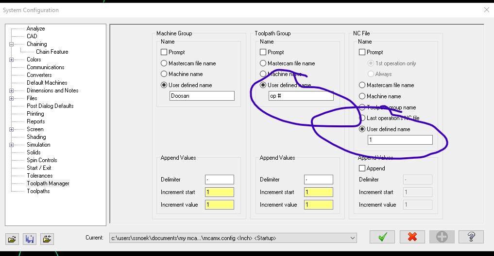
You can get your tool path groups to self number like this.
 1 point
 -
Damn.. this has to be close to the reviving the oldest thread award?0 points