Leaderboard


Popular Content
Showing content with the highest reputation on 01/24/2023 in all areas
-
Greetings! I'm a big proponent of Varco Reports (http://varcoreporting.com/) to generate setup sheets. It's what I use to generate setup sheets and tool lists for all of my customers.2 points
-
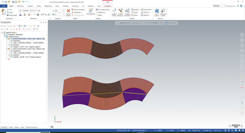
When flowline was first released, it only handled a single surface. Then was added the ability to handle multiple drive surfaces by flowing along a row of surfaces (crossing over one shared edge between two consecutive surfaces). Later, was added the ability to handle a wider set of connected drive surfaces such as multiple rows or a grid or a quilt. The "single row only" allows you to revert back to the first algorithm, should that do a better job (on a single row) than the latest quilt or grid approach. The top toolpath is a single row (using the single row option). The bottom toolpath is a grid or quilt with "single row" unchecked.
 2 points
 -
In-House Solutions is excited to release all of our Mastercam 2023 training material free of charge. You are free to download the pdf training material and Part files but check back often as we do update this material regularly. This is the same training material we use in our training classes you just don’t get the expert trainer to walking you through it. https://www.inhousesolutions.com/resource/mastercam-2023-training-links/?fbclid=IwAR37BKhkMZ2SFG6_3x2l54fH-hdj9hCVQti4mQtgs0mPhoYu_uPEH1h_SYc1 point
-
I think they have been working on it for the last 10 years Yes it is possible but you need to add a bunch of code to the post. If you are an experinced post guy that should not be too hard if you are not then paying somebody to do it will be a better solution1 point
-
We have the small lang. It works but you have to make a few facing passed to clear big pockets. The center doesn't really provide push because the blade isn't there. I put an approximate tool length in and tweak it as needed. It will suck loc lines into it and destroy itself if they are too close.1 point
-
Great explanation.1 point
-
Try removing pspindleout, after the [if not(opcode$ = 3 & nextdc$ = 7), pspindleout], e$ see example below. Please note you may need to do this at psof$ and ptlchg$ depending on your post. if safe_index, [ if lock_codes = one & not(index) & rot_on_x, pbld, n$, *sunlock, sunlockcomm, e$ pbld, n$, pgear, e$ pbld, n$, *sgcode, [if not(index), sgabsinc, pwcs], pfcout, [if not(opcode$ = 3 & nextdc$ = 7)], e$ if lock_codes = one & not(index) & rot_on_x & cuttype = 0, pbld, n$, *slock, slockcomm, e$ pbld, n$, pfxout, pfyout, e$ pbld, n$, pspindleout, e$ #NEXT LINE ] else, [ if lock_codes = one & not(index) & rot_on_x, pbld, n$, *sunlock, sunlockcomm, e$ pbld, n$, pgear, e$ pbld, n$, *sgcode, [if not(index), sgabsinc, pwcs], pfcout, pfxout, pfyout, [if not(opcode$ = 3 & nextdc$ = 7)], e$ if lock_codes = one & not(index) & rot_on_x & cuttype = 0, pbld, n$, *slock, slockcomm, e$ pbld, n$, pspindleout, e$ #NEXT LINE ] phsm1_on #must remain before G43 pbld, n$, "G43", *tlngno$, pfzout, scoolant, e$ ]1 point
-
G68 has nothing to do with Center Of Rotation per se and G68.2 allow you the ability to track and program nowhere near Center of Rotation. In G68, the X, Y, and Z on the function call are the point about which you are rotating your coordinates. The R is the rotation angle. In G68.2 the X, Y, and Z are the relationship to the part origin the following program section beforenitnis canceled. The I, J, and K are Euler angles (if no P is specified) and they the rotations around Original Orientation Z, Original Orientation X, new Orientation Z to calculate the new orientations. If there is a P (can't recall the number off hand) then you can specify the order of rotation Q123 would be rotation around X, Y, and Z. Q321 would be Z, Y,and X. etc... G68.2 relies on parameters to define the machine kinematics. Combine that with a work offset and the control calculates every position in every orientation and rotation. HTH1 point
-
Use "finish passes" for depth cuts. This will create depths that do not fluctuate.1 point