Leaderboard


Popular Content
Showing content with the highest reputation on 07/06/2023 in all areas
-
And everyone is going to use what they prefer. I am just saying there are things inside of mastercam I can do that My counter part in solidworks cannot. I have been using mastercam to design and make parts ever wince they released solids in Version 8? or was it 7? Anyhow, little things like using similar geometry from a solid I already have, I can import all that geo and get to work on a new part. Anyhow it works for me, I am able to pull off some great designs. Been able to model an organic looking dragon biting the barrel of a paintball gun inside mastercam. So basically you can do anything you want if you understand it well enough.3 points
-
Yeah, a custom hook would be the way to do it, and it definitely sounds like one of those "really easy to get 98% functionality, really bloody annoying and time consuming to get the last 2%" kinda things Perhaps talk to @byte?2 points
-
I'll keep an eye out for when it changes. Seen it a few times so at least now I'll know what to look for.2 points
-
It looks like your linking page is set to 2D, not 3D. When you have 3d contours and choose 2d, your only option is to force everything to an absolute (not automatic) Z depth. Try changing the Cut Parameters > Contour Type drop down back to 3d.2 points
-
I know people complain about modeling in Mastercam, but I prefer Mastercam to most anything else. I can do things faster than my counterpart in Solidworks. Especially if I have a similiar product and I just want to modify. Now I do wish we could pull solids from a linked location like solidworks does. So if I make a change it would modify all the reast of the files using that file.2 points
-
For those using 2024, update 1 is available. Upon launch a pop up appears informing you of just that.1 point
-
Purely from a user perspective, I have used MC, Unigraphics/NX, Solidworks, Inventor and then finally, TopSolid, in that order. When I was a Mastercam user, I did some pretty hefty modelling in it, such as injection moulds, impellers, Impeller Blade dies, and all manner of 3D prototypes. I always stated that it was a good capable modeller, even in the pre Solids days. However, once I started using Unigraphics etc, I realised how much more productive full blown CAD modellers are, especially when making changes. Not to mention freeform modelling (notably variable fillets, and surfacing functions). However, while I was comfortable with Unigraphics/NX, I never got to grips with Inventor or Solidworks. Both those applications I really disliked using. When I started using TopSolid, I found the modelling and assembly management really good. Very easy to use, and very capable. What I find interesting nowadays, is when shops get TopSolid for programming (and have designers using Solidworks), once the design staff check out TopSolid, they always have positive comments about it, and to the point that the designers start to look at TopSolid closer.1 point
-
I mentioned in another thread that allowing levels to be "active" meaning visible AND selectable vs. non-active meaning visible but NOT selectable would have real beneficial use. Then there were jokes about CAD functions yadda yadda I'll say again, there is a use for this function.1 point
-
That's a training issue. I can't think of anything CAD that MC can do that SW cannot. But you're right. People will use what they're better at and what they prefer.1 point
-
I feel we keep dancing around this issue. The problem arises whenever you are working in a mixed field of solids and wireframe entities. When you want to move or trim or manipulate wireframe entities, as soon as you select them, the solid edges become dominate. You can turn of the edge selection in the selection box and everything is good until you exit the function that you were working in. Then when you try to manipulate something else, there's that solid edge default again. There seems to be no way to turn this off as a default. The guys in my shop Hate this. Absolutely ANNOYING! Way too much time spent turning this off. Did I mention ANNOYING? If there is a way to deal with this please tell. Not looking for a work around. We've been dealing with this for a long time. I keep hoping the next version has the fix. I'm on 2023, getting ready to install 2024. not getting my hopes up, but, Maybe!1 point
-
Oh to be young and foolish again!!!!!1 point
-
I do this with Operation Groups, and Sub-Groups, in the Ops Manager. Easy to track rotations/tools, when grouping the Operations. Then I can name my groups to convey information back to me, while programming and/or posting. This sounds fairly trivial to do with a script of some sort, but there would be no way to do this "dynamically". If you changed a tool, from T3, to T8, then you run into a situation where the comment doesn't update. Do you want the script to be able to read if there is an existing "T3" appended, and be able to modify that to the current tool number? Now you are talking a script that requires more coding.1 point
-
Maybe a bug with 2D/3D switch, when going into an operation for editing?1 point
-
No idea? I haven't seen that, but I haven't really used 2020 in 5 years or so? Maybe there's a bug or something that's causing it with certain geometry selections?1 point
-
Workflow in SW is way different than MC. I have both open at the same time most days. I prefer SW over MC for 90% of the things I do. Especially if I built the SW model with correct design intent. That makes doing edits really easy and associative. Once the model is in MC I typically make small edits there unless they need to be built/edited in to the assembly, then I'll update the model and re-import it to MC.1 point
-
MP supports a lot of options. Macros? Sure, depending on what you want to do. "Micro Machining" using small decimal values? Sure, it can support that also. You can support up to 9.9 digits (9 decimals before, and 9 decimals after, the decimal point.) But the Post must be configured so the XYZ, Feed, IJK (circle center) values (etc.) are modified for more precision output. Plus, you must go in the Mastercam Configuration File (for Mastercam itself), and enable the "System Tolerance", and set the tolerance to 0.000000001. You will (typically) get the most precision on the machine using Metric Mode. Doing this allows you to support Nanometer Precision output. Now, the issue you will also (typically) face, is how does Windows store the number as a floating point unit, and how Windows operates on very small numeric values, contributes to issues with Rounding in the output. You can utilize 'round_opt$' to influence "what internal routine does Windows use to retrieve and round numbers".1 point
-
Is there anyway this is a miscommunication and the original post means MC2024? X4 = 24 ... Maybe?1 point
-
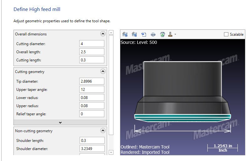
I've been using the High Feed tool and the manufacturer's step models for a couple of years now with no issues I like doing this because you get accurate stock when you save an STL file out of a Verify session. In the early days I had trouble with inserts getting crushed because the toolpaths were leaving cusps the tool was smashing into them during back feed moves . That problem seems to be solved now. In the example I've attached, I built a tool from an Ingersoll step file, then saved the geometry to a level and edited it a little Notice in my example that I've lied in the Cutting length setting.. If I set it correctly the walls in a Verify session look like they've been cut with a .08R button cutter. The resulting stl file was an unusable 120meg mess. After tweaking the defining geometry and setting the Cutting Length to .300 my Verify STL's have nice clean walls and yielded an 18 meg stl instead of a very messy 120 meg file
 1 point
 -
I have used highfeed cutters for almost 20 years and I have always defined them as bull endmills. This process has always worked. Why does it work I did a complete math breakdown of this many years ago and realized yes it leaving a little extra material when defining it this way verses the High Feed way, but when you see major performance hits in some areas of Mastercam using Highfeed Cutters for tool definitions I will stick with the KISS method here.1 point
-
He's chasing tail in Cuba right now. Will hit him up when he gets back. I remember him saying something about VBScript going byebye in Mastercam. I wonder if now might be a good time to toss out the old and busted and learn teh new hotness.0 points
-
Do you need to do that in the operation itself, or would doing it in the NC be good enough? That would be fairly trivial to do in the post. Edit: Colin beat me, dangit!0 points
-
most of our work instruction/setup sheets over the years have been pretty simple. Now days I'm finding that you have to write a step by step manual on how to set a job up and run the parts. I think that I spend more time on setup sheets attempting to write instructions and snap shots of parts than I do anything else. Back when I started in the trade, everything was text and you had just enough info to set the job up. It's almost to the point now where you need a video of someone setting up and running the job. I guess that's what happens when you have a generation of "machinists" who watched a few titan video's and think they're ready to go pro.0 points