


TFarrell9
-
Posts
95 -
Joined
-
Last visited
Content Type
Profiles
Forums
Downloads
Store
eMastercam Wiki
Blogs
Gallery
Events
Everything posted by TFarrell9
-
Do you have any videos on how to model this? I'd really like to learn how to create a dynamic solid like an impeller blade. I wasn't even sure it was possible in mastercam.
-
I modified the mill2 template (attached) and think it suffices. I modified the lathe template the best I could as well, but I wish it were more similar to the mill format. setup sheet example.pdf
-
@ThickChips Like you said, it's really for controlling the commanded feed rates for the C-axis by essentially mimicking a Y-axis. Without the use of G112 (polar coordinate interpolation), the motion and coordinates will still be correct, but the feed rates will be all over the place. Cutting in a circle would be somewhat okay (bad feed, but constant), but if you interpolate off-center, it will be excessively fast in one part of the cut and excessively slow in another.
-
I'm unfamiliar with Haas, but the post for our Doosan (fanuc) posted the same code where you're getting the "invalid code" and we've had no issues with interpolation on that machine, including using wear comp. Of course I'd have to run this code say for sure, but it looks fine to me. As for the first line of your code following the G112 command (where you get a bad plunge), try giving "clearance" a value and see if that corrects that issue, because it does on my post. I'd personally never mill any contour on a lathe without G107/G112. Edit: It ran fine on the Doosan other than where cutter comp is enabled due to lack of lead-in/lead-out.
-
Can you share a file or sample file? If it's a lathe, your post needs to be setup for polar coordinate interpolation. You enable it by using a switch in the integers. However, I assume it isn't a lathe because there isn't a C axis option in your rotary control. It's going to be hard to help without a file.
-
Are you having this problem with both of the default mill setup sheets? What about lathe?
-
I downloaded 2024 about and hour ago and I'm finishing up migration now. I keep the Shared folder on the company server, is this why my configuration never transfers and file paths are always wrong with migration? Every year, I have to re-do my configuration and correct all of the file paths because they default local, even though I transfer from the "old" Shared folder on the server into the "new" Shared folder on the server.
-
You're not using canned cycles here. I don't know what the M73 and M140 do for your machine, but if you put an M0 after the M06, it will stop the machine after the tool change (M06). I agree with millman though, you should contact your dealer so they can get you dialed in. They can easily make the changes you want.
-
I'd use a Manual Entry instead of a dwell, assuming you're saying the vacuum table shuts off at the end of the program. After the last toolpath: Router Toolpaths>Manual Entry>*type* M0 Then when the operator is done blowing it off, they can hit Cycle Start and the the remainder of the program will be ran.
-
Leave G-view alone when switching between two machine groups
TFarrell9 replied to SlaveCam's topic in Industrial Forum
This is annoying to me as well. I've just got into the habbit of restoring my viewsheet bookmark in this scenario, though.- 1 reply
-
- 2
-

-
If the tools in the machine are setup with the inserts facing the operator/control, and positive X is to the right, then yes, that should be the case.
-
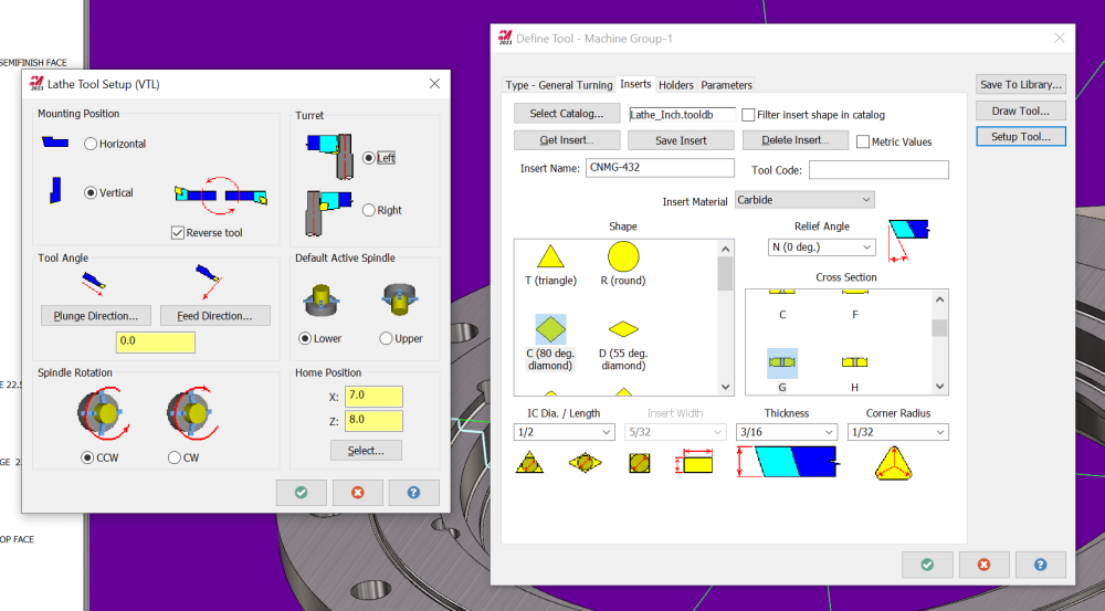
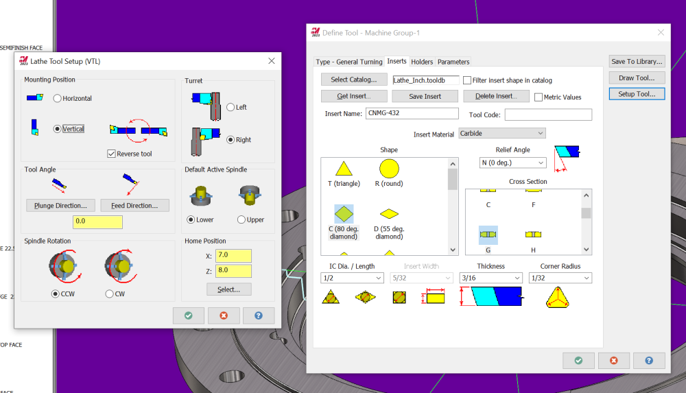
Both tool 3 and tool 4 are setup for "left" turret. Select "right". This will flip your tools around. If you wanted to use these same tools at that point, you will need to select your toolpaths on the left side of the part, rather than the right. Your X values will be negative of course, but it will be the correct side of the part. The way you have it right now is essentially just backwards.
-
your tool is setup for left turret instead of right, so it's "backwards".
-
Lathe Roughing - Go to ref point after each cut
TFarrell9 replied to ThickChips's topic in Industrial Forum
This. You can select the Tool Inspection box in the Parameters page and command whatever condition you want to use, such as per pass in your case. Edit: I haven't used it in Lathe, but you may need to edit your post processer for proper output at the inspection points. -
"Failure in stock definition" Error
TFarrell9 replied to [email protected]'s topic in Industrial Forum
This happens to me every once in a while as well. In a few cases, the stock setup will "forget" the stock definition I had selected, yet when reselecting it, will still give me this error. Closing and restarting Mastercam always fixes it for me.- 1 reply
-
- 1
-

-
- failure
- stock definition
- (and 1 more)
-
I haven't used it, but I was referred by someone (who machined some topographical maps) who used this website https://touchterrain.geol.iastate.edu/main Looks like there are quite a few settings to play with, but you can export it as an STL.
-
Here's your file, using optirest and how how you can force the tool entry from outside the part. I added a boundary on level 4. It's just a silhouette of the part, increased by .375" on all sides (just for the tool center to reach the outside edges of the part) with a made-up box area for the tool to plunge outside the part. This boundary is of course your containment boundary, with compensation set to inside and tool radius included. I also noticed you didn't have an arc filter enabled in this example, so I enabled it with a tolerance that equals 30% of your stock to leave (this creates much fewer lines of code and smaller file overall, in case you don't know). OPTIREST EXAMPLE.mcam
-
MCAMX9 MPHUR.PST needed for Hurco VM1
TFarrell9 replied to Simpleman67's topic in Post Processor Development Forum
I don't have those post files, but did you check your wear comp on the first machine that gave you that alarm? It sounds like a fanuc alarm where the wear comp value is too great for the radius to be cut. Another one is where G41/G42 are on the same block as G2/G3, but I believe the alarm wording is different than that. -
I have zero 5 axis experience, so I'm really curious to see what the experts have to say, but when I changed the output format to 4 axis, it smoothed it out a lot. I wonder what's causing all that strange motion?
-
I may be wrong, but this only works for known fixture positions, correct? We mostly do one-off large fabs and castings like OP, so the fixture macro I posted has worked great for us. But if things could be further streamlined with even less human input, I'm all for it. I know little about PST editing, but I was trying to find the COR values for G10 output in the PST file you shared. I thought it would be under pwritbuf9 with "new_x" (for example) or preadbuf9 with "b9_tox" (for example), but when I changed the values and posted from the mcam file you shared, the G10 outputs remained the same.
-
There are many ways it can be done, I believe some ways are easier depending on the machine. For some, you could just probe your pallet, which would be the simplest in my opinion. If you can't probe your pallet/table, use a test bar with a known gauge length (or any true-running extended length holder in the spindle, or your spindle quill on a boring mill) and get your spindle center as close to X center (over the table) as possible. Place a test indicator on the table and touch the side-tangent of your test bar to indicator zero (or spindle quill), clear your X origin on the control. Rotate the B axis 180*, touch the test bar to the indicator zero, split the difference of the relative distance measured on your control and move your X axis to that value. Move your test indicator to the test bar and start the process again. You may need to do this a couple times until you no longer need to move your X axis to get the same reading for B0 and B180. This is your X center of rotation (the machine position readout for the X axis). Once you have your X center of rotation, rotate the B axis 90* and touch the end of the test bar to your test indicator zero. This is your Z center or rotation, subtracting the known gauge length of your test bar.
-
Machine center of rotation is going to vary from machine to machine, it may or may not be at home position. For example, one of our horizontals' X center of rotation is zero, otherwise arbitrary numbers. Do you know how to check for center of rotation?
-
I use this on our horizontals with fanuc controls. Simple and reliable, easy for the operators to understand. In this instance, #530 is X center of rotation and #531 is Z center of rotation. Edit: Your "original" (#100 and #101) work offset and B axis value are your base (WCS) offsets. Enter your desired work offset value in #102 and desired B-angle in #103. Run the program and your desired offsets will automatically populate. Offset Calculator Macro.nc
-
Advanced drill cycle will give you the most control.
-
copy and paste a 3d tool path
TFarrell9 replied to keith tow's topic in Machining, Tools, Cutting & Probing
That's quite strange that you're losing the geometry as that shouldn't be happening....can't say I can help you there. But, I can tell you that you don't have to reselect geometry. With the toolpath folder expanded, right click on geometry and drag and drop it in the desired toolpath's geometry section and a dialogue window will pop and asking you to choose "add", "replace", etc.

