gms1
-
Posts
789 -
Joined
-
Last visited
-
Days Won
5
Content Type
Profiles
Forums
Downloads
Store
eMastercam Wiki
Blogs
Gallery
Events
Everything posted by gms1
-
Man..... so true!!!
-
It is very frustrating. It works the same way with the new Active Reports....
-
Yeah that's exactly why I brought up this thread. I started making a new right click menu for x6 and started pulling my hair out cause I couldn't find that nice 1 click button for the hst paths. I just threw one in there and Ill just change as I go.
-
thanks pat
-
I'm hoping I just cant see it but are the x5 style 2d hst and 3d hst toolpath icons/managers installed with x6? I really liked the fact I could click on one button to do all of these toolpaths instead of all these separate icons.
-
This only works with legacy style coolant??? Is it possible to turn this off then?
-

Holder Definitions for Standard Surface toolpaths
gms1 replied to CamMan1's topic in Industrial Forum
That's really disappointing if they didn't include holders for the good surface toolpaths in X6. Was really hoping to finally get that functionality for my Active Reports -
X5 MPMASTER OUTPUT RIGIDTAP CODE FOR FADAL
gms1 replied to Justin Beebe at Folsom Tool's topic in Industrial Forum
Justin look for this switch near the top of the post rigid_tap : 0 #0 = Floating tap output, 1 = Rigid tap output (suppress spindle output and output M29) Set that bad boy to zero and that will put your speed output back in the first line and remove the m29 line. I've never used a Fadal so I don't what M90 does. You may have to add something to get that output. -
Well that was far easier than I thought it would be to change this. I basically rewrote some of the pwcs post section. First, I changed the variable format of g_wcs: fmt H 4 g_wcs #WCS G address Second, I rewrote some of the pwcs post section: pwcs #G54+ coordinate setting at toolchange if wcstype = two | wcstype > three, [ sav_frc_wcs = force_wcs if sub_level$ > zero, force_wcs = zero if sav_mi9 = 1, workofs$ = sav_workofs if workofs$ < 0, workofs$ = 0 if workofs$ <> prv_workofs$ | (force_wcs & toolchng) | sof, [ if workofs$ = 0, #new code section 10/13/2011 gms [ g_wcs = workofs$ +1 *g_wcs ] else, [ g_wcs = workofs$ *g_wcs ] ] 2 different options for handling 0 (or default) output and the second is just to output the actual number input in the work offset box in mastercam. Yes the values look like H1,H2,H3,H15, etc...
-
Unfortunately I use many work offsets in my programs. But this does give me a starting point to changing this output, thanks Keith
-
I want to have my Okuma OSP post output H1 for the default setting (-1) or 0 in the work offset box. On Fanuc's this would output G54. How can I change the mpmaster post to output H1 instead of G54?
-
Some tool manufacturers have made tool libraries with default values for Mastercam. If you want to use one of these tools just right click in the tool box window or click the big 'Select library tool...' button. At the top of that screen is a little folder icon, click that and select a library from the list. You should see a bunch of them. Keep in mind that some of the libraries that manufacturers made are specifically for lathe or mill, not both.
-
Custom Sub Programs Posting to End of Program
gms1 replied to huskermcdoogle's topic in Industrial Forum
hmm... maybe do it by a misc. integer? This would go in your peof$ section: If mi10 = one, n$, "CODE HERE", e$ -
You do realize you are posting in threads from 4 years ago yes?
-
I don't understand why the tl_chuck output was removed since I use that for my setup sheets and doesn't pertain to tool holders. If we could get that and the # of flutes put back into the setup sheets I'd be a happy camper.
-
Always use top to do any stl work. Make sure stock view and safety view zone are set to top as well in your machine definitions. Draw or import the part to print datums if defined. Add stock. These 3 rules I follow religiously on every file I make. I have files with MANY machine groups, toolpath groups and WCS setups. I sometimes use solids for stock setup, sometimes stl models. All depends on whats available or quicker. Only thing that sucks is I can't do the same things I do for our verticals as I do for our horizontal. Transitioning from a vertical setup to a horizontal setup can be a bit of a pain! edit:: WCS is really the key to removing a lot of headaches with stock placement.
-
Hey all, I'm trying to setup some default .formula files for different materials and it's reading the values I'm putting in the different groups correctly. Some of them are, some are not. <?xml version="1.0"?> <HST_Formula_Data xmlns:xsi="http://www.w3.org/2001/XMLSchema-instance"> <toolpath name="Core roughing" target="COREROUGH"> <page name="Cut parameters" target="CUT_PARAMETERS__PAGE"> <group name="Stepdown" target="STEPDOWN__GROUP"> <param name="Stepdown" target="STEPDOWN">(@DIAMETER * 0.10)</param> <param name="Min stepdown" target="MINIMUM_STEPDOWN">(@STEPDOWN * 0.10)</param> <param name="Max profile stepover" target="MAXIMUM_STEPOVER">(@DIAMETER * 0.33)</param> </group> <group name="XY stepover" target="XY_STEPOVER__GROUP"> <param name="% of diameter" target="PERCENT_DIAMETER">33</param> <param name="Max" target="PERCENT_MAXIMUM">(@DIAMETER * @PERCENT_DIAMETER)</param> <param name="Min" target="PERCENT_MINIMUM">(@PERCENT_MAXIMUM * 0.55)</param> </group> <group name="Smoothing" target="SMOOTHING__GROUP"> <param name="Max radius" target="MAXIMUM_RADIUS">(@DIAMETER * 0.05)</param> <param name="Profile tolerance" target="PROFILE_TOLERANCE">(@DIAMETER * 0.01)</param> <param name="Offset tolerance" target="OFFSET_TOLERANCE"> Dim Offset Dim Constant Constant = 5.0mm If @TOOL_TYPE = @BALL Then Offset = @CORNER_RADIUS * 0.15 * 0.2 ElseIf @TOOL_TYPE = @BULL Or @TOOL_TYPE = @FLAT Then Offset = @FLAT_RADIUS * 0.2 Else Offset = @DIAMETER * 0.5 * 0.15 * 0.2 End If result = Min(Constant, Offset) </param> </group> <group name="Keep tool down within" target="KEEP_TOOL_DOWN_WITHIN__GROUP"> <param name="Distance" target="KEEP_TOOL_DOWN_DISTANCE">7.0mm</param> <param name="% of tool diameter" target="KEEP_TOOL_DOWN_PERCENT">(@KEEP_TOOL_DOWN_DISTANCE / @DIAMETER * 100)</param> </group> </page> First problem is "Profile tolerance" is still reading the default tool from the operation defaults I set up. I want that value to calculate from the diameter tool I choose, not the default tool. Now the values above this calculate correctly like stepdown, minimum stepdown and maximum stepover all work. Second problem is "Keep tool down within" doesn't work at all. Right now keep_tool_down_distance is 7mm but I've tried everything (english values, formulas etc...) and it still shows the same value no matter what I put in there. Then keep_tool_down_percent doesn't work of course because its reading the distance value, divided by the default tool diameter(wrong) multiplied by 100. I havent gotten past these 2 issues but I'm sure I will find more issues. Am I just missing something simple? I have Settings - Configuration - Toolpaths - Automatically calculate HST defaults turned off, lock feed rates is turned off as well. edit:: I would also like to get a hold of some kind of xml layout for ALL the options in these toolpaths and how the options are labeled with syntax. Is this possible?
-
Sorry for the thread necro Is it possible right now to create my own tooldb from scratch using sqlite? If it is possible, how on earth can I start using this sqlite expert to create a tooldb and fill it full of data that makes sense? Looking at the mill-inch.tooldb in sqlite expert I may as well be reading hieroglyphs in french! Any good books or something on learning this new language?
-
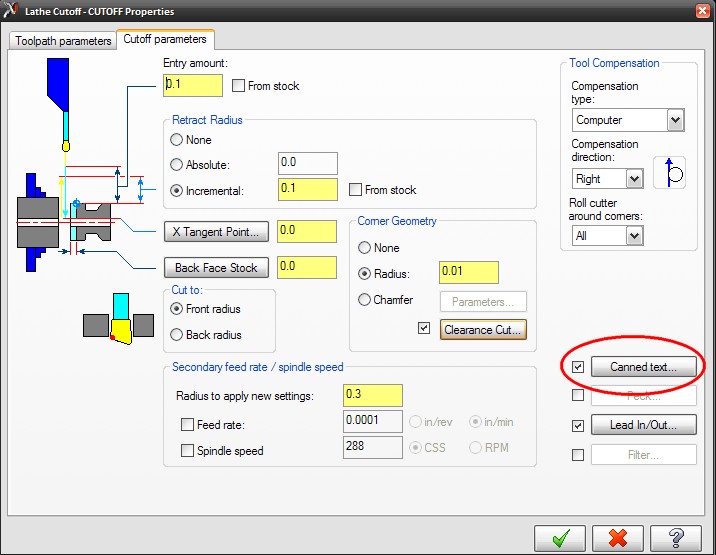
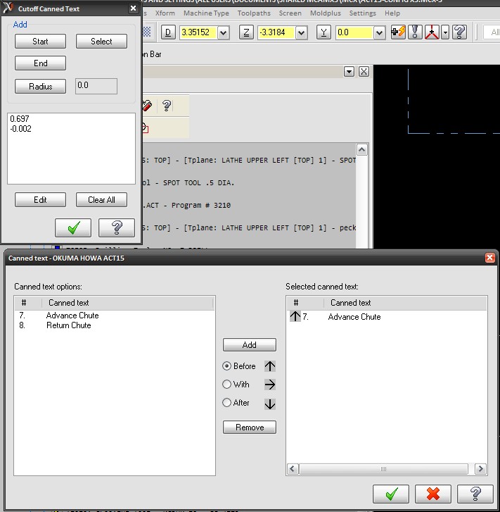
JP--- I'm about to go that direction, this is highly frustrating. I was thinking it would work using the stock post..... guess I was wrong. Colin--- I setup the breakpoint and watch for strcantext and sure enough it showed it cycling through that breakpoint a few times adding the extra commands and I see line 1025 a bunch of times with a bunch of zeros in a line in the NCI file. Here is my issue though, how and why is it adding those in?? I am using the stock post that came with X5 and I am using the built in option in the cutoff tool path to set canned text options where I want them in the code. How can I turn off the extra commands?
-
its there in my last post. Its not the whole section, but nothing after what i pasted there affects the output.
-
That section I changed just fine, its just adding code and I have no idea where it's coming from. No section of the post tells me to output that m16m00 stuff. # Chute M code selection sm73 : "M86" #Chute retracted sm74 : "M87" #Chute engaged schute : "" #Target string fstrsel sm73 chute schute 2 -1 It has something to do with the pcan section I believe but changing stuff there doesn't work. The chute advance and retract are cantext$7 and cantext$8. pcant_out #Canned text - build the string for output #Assign string select type outputs if cant_pos < three, #cant_pos indicates canned text output [ #Assign string select global variables if cantext$ = 3, bld = one if cantext$ = 4, bld = zero if cantext$ = 9, exact = one if cantext$ = 10, exact = zero #Build the cantext string from strings if cantext$ = 1, strcantext = strcantext + sm00 if cantext$ = 2, strcantext = strcantext + sm01 #Build the cantext string from string selects if cantext$ = 5 | cantext$ = 6, [ if cantext$ = 5, tlstk = zero else, tlstk = one rslt_upd = updstr (stlstk) strcantext = strcantext + stlstk ] if cantext$ = 7 | cantext$ = 8, [ if cantext$ = 7, chute = zero else, chute = one rslt_upd = updstr (schute) strcantext = strcantext + schute ]
-
I cannot for the life of me figure out where this post is getting the output below . I grabbed the default lathe post that came with X5 to do this. I edited the schute M code section to the right m codes for my machine (m86/m87) but I keep getting this output with it that I can't find anywhere. The post debugger doesn't help either since these commands aren't anywhere in the post. Why am I getting m16m00 and m17m00 output on these lines?? All I want is M86(Advance Chute) and M87(Retract Chute) to output. Any ideas? ( CUTOFF ) G50 S3600 G96 S288 X1.4 Z-2.125 G1 X1.12 F.0015 G0 X1.4 X1.6 Z-2.105 G1 X1.4 M86M16M00 <---m86 is correct, m16m00 should not be output! X1.3941 X1.2 G3 X1.16 Z-2.125 I-.02 G1 X-.0037 M87M17M00 <---m87 is correct, m16m00 should not be output X-.02 X.18 G0 X1.4 M9 G28 U0. W0. M5
-
This change was easier than I thought if lturret$ = 1, #added 5/24/2011 gms [ pbld, n$, "G13", "(UPPER TURRET)", e$ ] if lturret$ = 0, [ pbld, n$, "G14", "(LOWER TURRET)", e$ ] I added this to my ltlchg$ section of the post and it works like a champ!
-
Thanks for the input guys. I was hoping I wouldn't have to bother the customer with it since asking them for anything is a PITA.
-
I know moldplus, verisurf has an mbd translator for catia files. What I dont know is how does it work. Would I have to request my customer do something with the files to get this to work in mastercam, or can I just open a catia file and all the gd&t will show up automatically.