The Cathedral
-
Posts
736 -
Joined
-
Last visited
Content Type
Profiles
Forums
Downloads
Store
eMastercam Wiki
Blogs
Gallery
Events
Everything posted by The Cathedral
-

Tap that was etched wrong
The Cathedral replied to Johnny M's topic in Machining, Tools, Cutting & Probing
I've received bad marked taps before. It was just one in a box; the rest were correct, but it definitely did not have the right etching on it. This was a well-known company, too. Sucks to have that happen. On the plus side, at least you know the taps are strong! -
Work Order forms
The Cathedral replied to Matthew Hajicek - Singularity's topic in Machining, Tools, Cutting & Probing
Here-- When is the due date for this part? Two weeks ago Can I purchase special tooling if I need to? No You accidentally routed a lathe part to a vertical machine. Can I move it back to the lathe department? Don't tell me how to do my job. Is this print finalized or is it bound to change? It's finalized. Make it. Are you sure? YES. Are you really really sure? YES. Wait, no, make this groove deeper. This engineer drew geometry that is physically impossible. So physically impossible it can't even exist in this dimension of reality, and I'm convinced the engineer is Cthulhu the Demon from the great beyond. Can you contact the engineer and have him revise this? What, you can't program that? What the hell do I pay you for? etc.... -
If you're saying the simulation looks good but the code is bad, then the problem is probably how your post is calculating the rotation. Just by looking at your pictures it seems that neither the default Mastercam world origin nor your created plane origins actually lie on the center of rotation. Someone correct me if I'm wrong, but in my experience the axis of rotation should lie along a world origin axis, especially if you're doing 3+1 toolpath and not using mult-axis.
-
You'd have to use the Renishaw probing routines and macros, without a doubt. The Prod + software was written by Renishaw for Renishaw and if you wanted to use different macros, you'd have to edit the Renishaw post, and that is heavily encrypted. As for using a different brand probe body, while I couldn't speak for experience, I would say that as long as it only uses a G31 skip signal to trip the machine, it might work.
-
System configuration > Files > check the box next to 'Include bitmap in file when saving'
-
Osp7000 lathe coolant issues
The Cathedral replied to mkd's topic in Machining, Tools, Cutting & Probing
M602 only works with HSK or Capto spindles. If you don't use those, it doesn't work. -
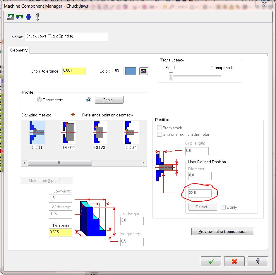
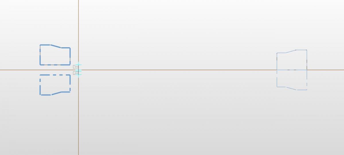
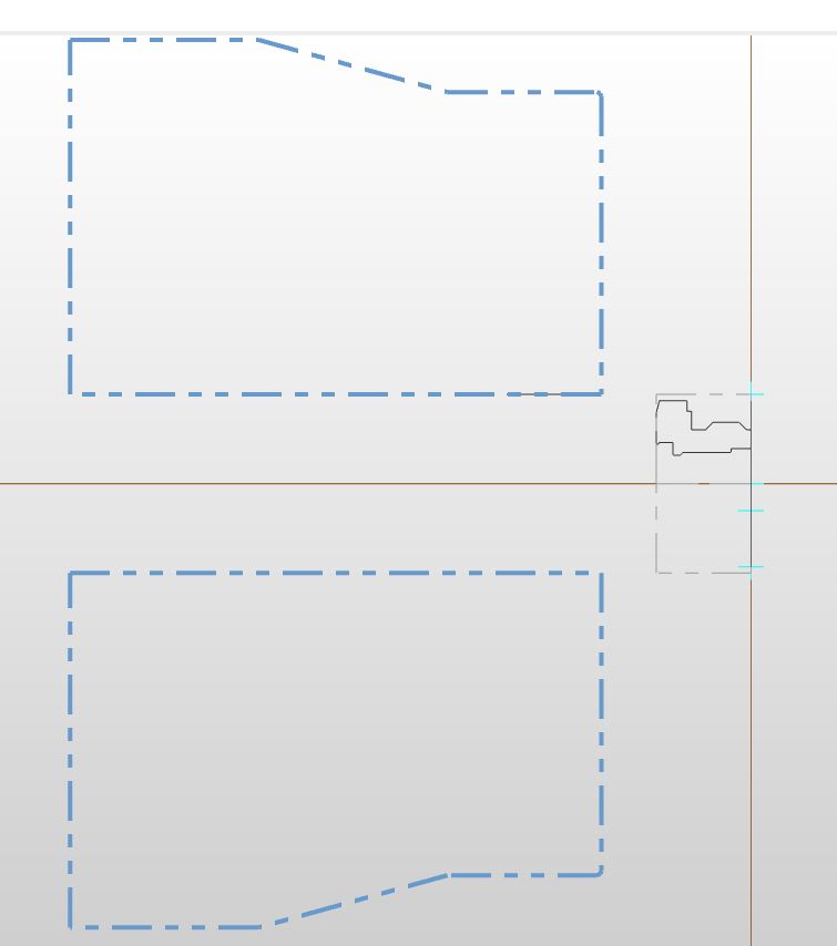
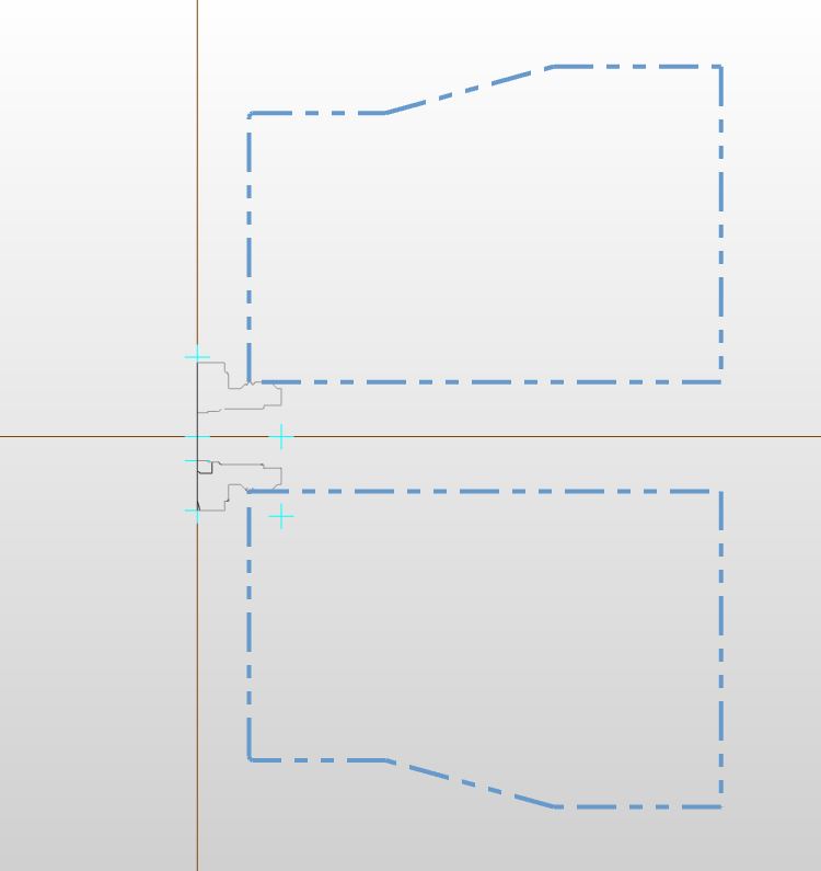
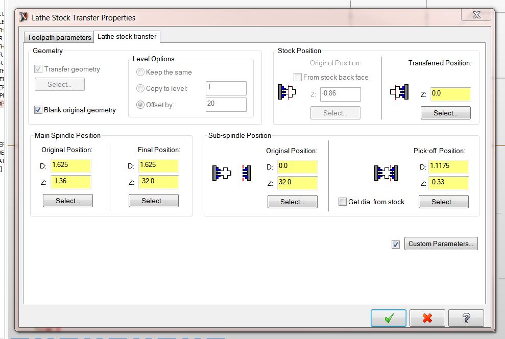
When you define your subspindle, make sure the original position is far away from the main spindle. That way there is no interference. Since I use a chain to define my chucks, I have the sub spindle chain drawn 32 inches away from the main. The sub spindle should only approach zero during a pick off procedure. Also, the way that I program, the part does only move on-screen to the other side of zero. Again, this is so I don't have to create any more planes or zero points, and I just use the default TOP WCS. I know it is not the way most people program, but I have found it to be leaps and bounds easier than the way most people program. Sub parameters before pickoff after pickoff


-
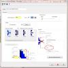
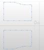
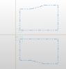
There are many ways to approach this. For me, I started using Mastercam using only Mill and when I got into lathe, it was non-stop frustation and keyboard-throwing. When you approach lathe, you have to pretty much throw out everything you know about Mastercam. I had to keep playing with it until I found a method that worked for me. Now I do spindle transfers all day long with no problems. I despise the idea of having to sets of part geometry 20 inches apart on my screen and having to make multiple WCS zeros, especially since lathe handles everything so damn wonky. So, I only use one: the default TOP WCS zero point. Assuming you program using Z zero at the face of the part- When I define my stock, my stock length is only the length of my part, not longer as if to represent a bar. If I'm doing a chucker or using slugged material, it is the length of the material, but only then. I define my stock only in the main spindle, and I define my chucks: the main chuck in position, and the subspindle 32 inches to the right (the only time I ever use this geometry is for defining the spindle, after that it's blanked out.) To do a transfer I set my options like the last picture below. Notice the main spindle position. I have it move from my originally defined position, to negative 32 inches, because in the actual machine, it will end up being that far away. So, my geometry goes from looking like the picture name Position 1, to looking like Position 2. Because the main spindle is 32 inches away, there is no interference from tools or stock. And using the same WCS lets me keep my sanity. One thing I have to note is that we use a macro for the pick/pull/cutoff procedure in the machine. I modified my post to pull all the relevant information from the MISC OPS - STOCK TRANSFER parameters to feed the macro, and I use the custom parameters to modify feeds and speeds of my cutoff tool. This lets me use the same procedure for every part I make, including chucker parts where there is no actual cut off. Hope this helps.
-
Osp7000 lathe coolant issues
The Cathedral replied to mkd's topic in Machining, Tools, Cutting & Probing
Ah. I do not think you are programming that correctly. The MT code is a pre call; you use it to stage the next tool to be used, not to call up the tool you are about to use. Using it like you are doing is not calling up any tool offset or information, it it merely cycling the tool into position in the ATC. You need a tool activation command (on our Macturns, it's TL, on our Multus it's TD). You are sort-of activating it with the dummy "T100" command, but all you're doing is calling up the information for tool 100, not the tool you are using. For example, this is how we program, assuming tool 21 is already in the spindle: N21 (.4375 REAMER) TL=2121BT=1 MT=0701 M110 M13SB=836 M8M175(M175=THROUGH THE TOOL COOLANT ON) G00 X 50. Z 1.520 G00 X 3.000 G138(Y-MODE) G00 X 0.550 Y 0.031 G94 G181X -0.650 Z 1.520 Y 0.031 C 0. I 0. F 6.688 G180 M12(STOP MILLING SPINDLE) M146(UNCLAMP C-AXIS) G136(CANCEL Y-MODE) M109(CANCEL MILLING MODE) G00 X 50. M09 M174 G21HP=4 M321(PUT TOOL #07 INTO SPINDLE) -
Osp7000 lathe coolant issues
The Cathedral replied to mkd's topic in Machining, Tools, Cutting & Probing
You don't set the coolant options, just the tool type. Then OSP knows what coolant codes to use with that tool. We set ours in the ATC Tool Data page; but again, ours is a much newer control so it is probably different. -
Osp7000 lathe coolant issues
The Cathedral replied to mkd's topic in Machining, Tools, Cutting & Probing
On our Macturns/Multus, there are different codes for mill tools and lathe tools, all depending on how the tool is defined in the control. I'm not sure about the control you have as our controls are OSP100, 200, and 300. The BA only sets the angle of the head, it doesn't do anything else. When you define a tool in the control, you have to set its type, shape, and default orientation. It's the type of tool you call it that defines what coolant works. Mill tools can be set as lathe tools, lathe tools can NOT be set as mill tools. Thru spindle coolant; Lathe tool: M08/M09, Mill tool: M174/M175. Flood coolant (Turret nozzles); Lathe coolant 3: M262/M263, Mill tool: M08/M09. -
Screw on slotting tools
The Cathedral replied to Mic6's topic in Machining, Tools, Cutting & Probing
Iscar does make a full radius indexable t-slot head, but they don't have it as a single category in their catalog. You just have to dig through to find the ones with the corner radius = half the slot thickness. However the biggest I can see is .236" thickness. -
In the Transform Operations Parameters, under the Mirror tab, there is a box to control the Cutting Direction. Click on the ?-mark on the bottom and when the help pops up, click on the Field Definitions tab. In there it explains fully how each option works, with pictures to help.
-
Ok, but what about the cycle time? If I could machine a part in -32 seconds, I'd be rich.
-
I don't believe you can change it. For me, I find all that information pretty much useless, especially when I use a canned threading cycle and it give me feed in the negative, and cycle time in the negative. That's something I absolutely do not understand.
-
Lathe stock and machine group question
The Cathedral replied to Matthew Hajicek - Singularity's topic in Industrial Forum
Holy cow I never knew about that! Wow, that's going to help out a lot going forward! -
e is spanish for P
-
Screw on Endmills *Long reach*
The Cathedral replied to dstryr's topic in Machining, Tools, Cutting & Probing
I hate it when I come across a 19mm bolt and all I have is a 3/4" wrench. Can't do anything. -
I'm glad you got it running. Just to add to your previous question: we have a TS27R tool touch off probe, and I calibrate the spindle probe using that. I prefer to do it that way so I know my probe was measured the same way my tools are measured. When we calibrate the probe, we just do "radius + offsets".
-
Yeah, the Prod+ has it's own special macros that you have to load and use. You have to write a calibration program using Prod+ and run that in the machine and it will store the calibration data in the common variables. The "Inspection" macros that you can modify at the machine don't work with Prod+. Thankfully, the calibration process is pretty easy. We use a lot of different stylus sizes, so I made up standard calibration programs for each size. Whenever we need to switch out a stylus, we just load up the relevant calibration program and run it using a standard procedure. It takes no more than five minutes usually.
-
I guess that means I'm no help here. We control our indexers with RS232 using a macro and the DPRINT[ ] commands in our Fanuc controllers; the only other languages I'm fluent in are Okuma OSP and Mitusbishi MELDAS.
-
Do Hurco machines use a Fanuc control?
-
That's definitely not an MFIN code then, that only uses a 4-pin plug. Check for any code that isn't X, Y, or Z
-
When we run into that error, it is because the Productivity+ program was programmed using a different stylus that what the machine is calibrated for. So, if I had a machine that has a 6mm probe stylus in it, and try to dump in and run a program that was made for a 2mm stylus, that's the alarm we get. Make sure your stylus' are the same (specifically, the ruby diameter.) Are you new to using Productivity+ ?
-
Is it your indexer or are you just borrowing it? What brand is it? What brand of machine is it going on? is the machine it's going capable of doing 4th axis?