The Cathedral
-
Posts
736 -
Joined
-
Last visited
Content Type
Profiles
Forums
Downloads
Store
eMastercam Wiki
Blogs
Gallery
Events
Everything posted by The Cathedral
-
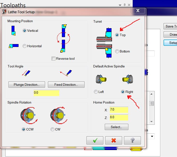
Interesting. It works for me without fail. What version are you using? X8? Just to clarify, you have your tool defined like this, right?
-
The default spindle is defined by the tool, not your plane/wcs. I usually have duplicates of most tools, one defined in the "setup tool" tab as main, the other as sub. So depending on which spindle I'm on, I use a different library and it automatically assigns it correctly.
-

Flat Bottom Tooling
The Cathedral replied to The Cathedral's topic in Machining, Tools, Cutting & Probing
I wish they were common sizes. They're all under .459" too. I have RFQ's out, but I've yet to get one back. We're willing to pony up and spend to have a large quantity of tools custom made for the FBCB's, it looks like we might have to for the drills just to make sure they're on hand when needed. Thanks for the info everyone. -
I'm rockin' an M6800 myself and it'll blow through any project I put on it, even with two extra monitors to run.
-
On our Okuma LT's with P200 / P300 controls, the code is M808 (cutting feed interlock release OFF) and then when you're done M809 turns it back on. On our MA400HA horizontal mills with P100 controls it's M130. I'm not sure which one it will be since you're on a mill/turn; we have a couple Macturns and Multus' but I've not used that function on them so I don't know.
-
It shows parallel to the axis because your tool plane is right side, which is parallel to the axis. Your tool plane should be top. You should unroll the geometry onto the flat plane ( so it will look like a very long straight line), toolpath it, then roll it using axis substitution. Or, if you have the multi-axis add on, you can just toolpath it directly.
-
Depending on what type of control you use, you're going to have to put a code in do do a feed move with zero spindle speed. EDIT: I see you're using a Mazak; I don't know about those but you do have to on a Fanuc or Okuma.
-
Flat Bottom Tooling
The Cathedral replied to The Cathedral's topic in Machining, Tools, Cutting & Probing
Those looks like some pretty sweet tools. Unfortunately they're all carbide; I'm starting to think off-the-shelf HSS flat-bottoms are a pipe dream. -
IIRC there was a thread about this not too long ago. What post/machine def. are you using?
-
Use Misc Ops > stock flip, or copy the geometry to another level and rotate it. Those are the easiest ways.
-
Yes there is. The WCS is calculated as a matrix and they are parameters that are passed to the post; you'll have to set up a variable to store the parameter, and the logic to decode that information into what you are looking for. I use it to output the angles for our external rotary indexers. They have to be programmed into the rotary control box by hand, so the post outputs the correct angle for the operator to punch in. If you're looking for a "full" rotary axis, you'd be better off using a post that was already designed for it.
-
Not to mention some machines have the entire spindle attached to the ballscrew by one single M6 screw on a collar. That's how our Daewoo DMV4020's are. Loosen up that bolt and vwooop! the spindle drops to the table in a split second. I know that has zero effect on rigidity but if you're worried about crashing, screwing up the Z would be the biggest concern.
-
Flat Bottom Tooling
The Cathedral replied to The Cathedral's topic in Machining, Tools, Cutting & Probing
Cool, thanks. That's what I'm looking for. I hope they have them in stock since I can't find them in any catalogs. I sent a request for more information. -
Flat Bottom Tooling
The Cathedral replied to The Cathedral's topic in Machining, Tools, Cutting & Probing
Thanks. I sent an RFQ to Internal so we'll see how competitive they are. We've never used they're tools before. Do you have a lot of experience with them? Not just the cbore, but other tools? I was looking at those Kennametals yesterday but we definitely need HSS. -
We have many special products where we use a custom version of Harvey Tool's flat bottom counterbore. These tools are flippin' awesome and are extremely well designed. The only problem is they require over 3.5 weeks lead time to make and are not what even a rich guy would call cheap. I was wondering if anyone had used tools like these from a different manufacturer and if so, who? Also, do any of you have a good source for flat-bottom HSS twist drills? I see Guhring and YG advertise it, but I can find no literature or part numbers on it. I'm hoping for some off-the-shelf stuff. Normally we grind our own but we need repeatability and quality for a new project.
-
NPT threadmills (at least the ones we buy) cut the taper as they cut the threads. We bore a straight hole to whatever minor diameter we need, and then threadmill away. I draw a custom tool that has a cutting diameter that the endmill has etched on it. We do it on everything from plastic to inconel.
-
The sample file you posted works fine for me using my Okuma LT2000MY post. No errors. Were you getting the error with the sample file as well?
-
I have something like that available here: https://youtu.be/dQw4w9WgXcQ
-
No I did not. Do you have a part file you can share? I can take a look at it and see if you have something set wrong.
-
On all our Fanucs the tool change is a subprogram called up by the M6. It's protected but inside of it is all the tool pot down/ up commands, tool change, etc. You can easily put a rotation command in there.
-
I've ran into several bugs but none so bad that I would stop using it. Most of the bugs have to do with the new functionality, and all the stuff that I'm already used to is working fine.
-
Has anybody cut an off center diameter with a CNC Lathe?
The Cathedral replied to Glenn Bouman's topic in Industrial Forum
You don't have to have a y to do it, but it does limit how much you can go off center. The further off center, the steeper the cutting angle becomes tangent to the surface. You'll get to the point where the off-center surface will actually hit the back of the tool. -
Did your computer install updates or did you install new programs? This was happening with X9--you probably updated something and that something replaced the .dll, not knowing several other programs use it. It has to do with Microsoft updating their .net redistributable. EDIT: JParis got it.
-
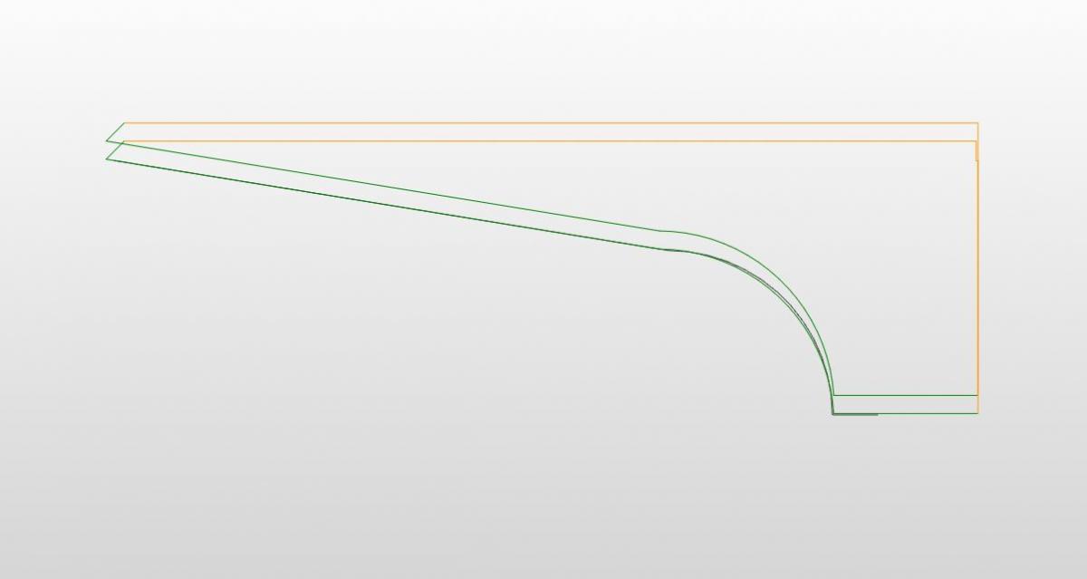
I think I understand. Adjusting the lead - in adds an imaginary line that is tangent to the start of the profile. When you have a full radius as the start of your profile, that imaginary line is drawn straight down accross the face of the part--it goes straight down in your x axis of movement. Mastercam ignores movements like that so you could set it to 100mm and you would see no change. What I would do is add an extra line of geometry and use it just for that toolpath. So, if I understand correctly, what you are seeing is like picture one below. In picture two I added the line, and then all of a sudden you can see the lead in adding the extra length.


-
Converting a 4axis vertical mill program to 4axis horizontal.
The Cathedral replied to danielm's topic in Industrial Forum
You could also just flip the machine on its side.