So not a Guru
-
Posts
2,327 -
Joined
-
Last visited
-
Days Won
7
Content Type
Profiles
Forums
Downloads
Store
eMastercam Wiki
Blogs
Gallery
Events
Everything posted by So not a Guru
-
CHANGE START/STOP POINTS ON COUNTOUR AND OTHER TOOLPATHS
So not a Guru replied to RustyG's topic in Industrial Forum
You can also edit the direction, as well as the offset direction in the chain manager for the individual toolpath. -
How do I change this? Mine always defaults to "selected order", but I want "point to point" as my default.
-
The top 2 icons determine your selection type. The left icon will allow you to select wireframe geometry, the right icon will allow you to select from solids (edges, faces etc).
-
Ok that makes sense. I didn't realize that, probably because I so rarely use the extended offsets.
-
It worked perfectly, thanks again. How does this work? I get the 1st part #100=Abs[#[5203+[20*[#19-101]]]], but I don't understand how subtracting 101 from the S value returns the correct offset register. Wouldn't #100=ABS[#[5203+[20*#19]]] work ?
-
Thanks John, I'll try it in the morning.
-
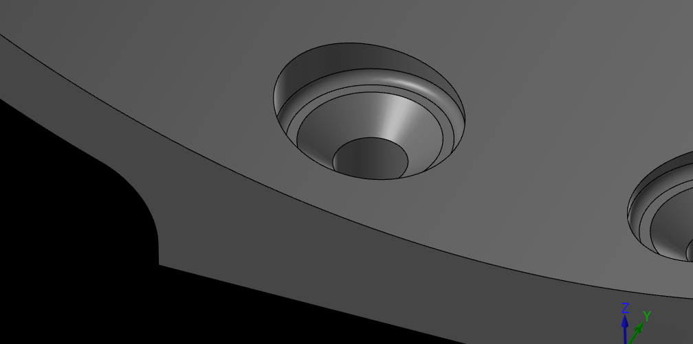
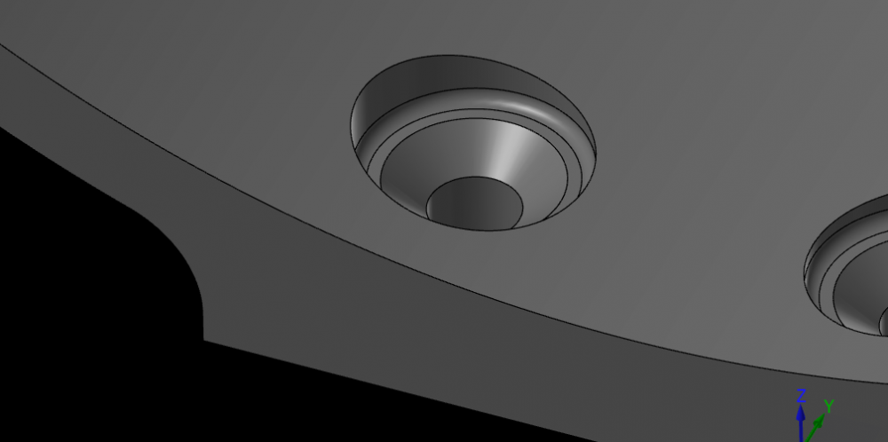
We have a part that has countersinks that are recessed into a curved surface. To measure c'sinks that can't be reached with a c'sink gauge, we usually use a gage ball & indicator to determine if the c'sink diameter is correct. Since this part has the c'sinks on a curved surface, we can't do that. So I thought I'd try my hand at using a probe & writing a macro to extrapolate the measurement. I can't seem to get it to work. The machine is a Mazak VCU500 with a Matrix II controller. Can anyone point me to what I've got messed up here? This is what I've got: (MEASURE CENTER OF PART "Z") /G53 Z0. /G53 X0. Y0. /G53 B0. C0. /T30 M06 /G0 G90 G54 X0.0 Y0.0 G43 H30 Z4.0 /G65 P9810 Z1.32 F50.(PROTECTED MOVE) /G65 P9811 Z0. S2. (SINGLE SURFACE MEASURE, STORE IN G55) /G65 P9810 Z3.5 F50. (PROTECTED MOVE) /G53 Z0. /M01 M00 (PLACE A 7/16" GAGE BALL IN THE CSINKED HOLE) (TURN THE RAPID DOWN TO 25%) (MEASURE THE TOP OF THE BALL) /G53 Z0. /G53 X0. Y0. /G53 B0. C0. /T30 T20 M06 /G0 G90 G54 X-0.50 Y-0.50 G43 H30 Z4.0 /G65 P9810 Z1.56 F50.(PROTECTED MOVE) /G65 P9811 Z0. S3. (SINGLE SURFACE MEASURE, STORE IN G56) /G65 P9810 Z4.0 F50. (PROTECTED MOVE) /G53 Z0. /T20 M6 /M01 #100=(ABS(#5243)) #101=(ABS(#5263)) #103=(#101-#100) M00 (CHECK THE 0.382" - 0.392" 100° CSINK DIA) (MACRO VARIABLE #153 SHOULD BE BETWEEN 0.2849 & 0.2891) (ADJUST THE OFFSET AS REQUIRED) (THE NEXT OP WILL RERUN THE PREVIOUS CSINK)
-
Now that I’ve had a minute to think about it, I wonder if this is how CNC software sets the perpetual license. When they give a new customer a trial license it would have to have an expiration date, this would be a way to accomplish that, since the date will never occur (the year is probably set to the current year). Still, it makes you wonder why it just started popping up today.
-
No, I check with our dealer, everything is good on all of our licenses, including our Moldplus add-on & 3rd part posts.
-
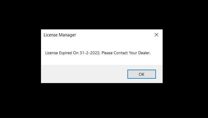
I came in this morning & when I opened MC I got this message. My file opened just fine after I clicked OK. But when I opened a new instance of MC, I got it again, so I rebooted my box to see if the issue might be something in windows. Nope, I get it every time I open a new session. Anyone else ever get this one? The last time I checked February didn't have a 31st, but the way we all seem to believe in alternate facts these days, maybe I just missed the memo .
-
I could be mistaken, but I think you just have to turn off the safety shield.
-
And if you right-click on it, it can exist on your PC.
-
Thanks Ron! That is exactly what I was looking for. Took me a minute to figure out how to locate the point, for axis control, but after I figured that out, my path was good.
-
That's pretty cool! But I was really hoping their was a way to do it with surface machining, I tried to use morph, but I couldn't figure out how to make it run in 4 axis.
-
Is there a way to cut the green fillet in a similar manner as the axis sub contour path? AXIS-SUB.mcam
-
1/4" high feed mills with CTS
So not a Guru replied to So not a Guru's topic in Machining, Tools, Cutting & Probing
I'm liking their selection, thanks for the tip! I don't see any speeds, feeds & DOC info on their site. Am I just missing it? -
To drive my threadmills, I've have been using the major diameter of the thread size I need. This is how I've done it since I started using MC and up until 2022 I always got good results, we always started with no radius offset, ran the path and checked it with a GO/NOGO gage. It was always undersized and we would then subtract the GO diameter from the NOGO diameter, divide it in half & adjust the offset. Most of the time that would get us a good thread, if not we adjusted until it did. Since 2022 that has changed. Now we have to create geometry that is at least 0.010" smaller than the major diameter! Even the we sometimes blow out the thread on the 1st pass. Did something change with the issue of 2022?
-
Anyone have a source for these? We've been using the Helical ones and they work fantastic, but they have been out of stock for over a month and our vendor has no idea when they'll be available again. Looking for something comparable to these: Helical
-
So I should modify my post (or have Postability do it for us) to output this: G56 G17 G90 G90 G43 H39 G00 A-18.435 C0. M03 S3500 G49 G68.2 X0. Y0. Z0. I180. J18.435 K0. G53.1 X3.75 Y18.3259 G43 H39 Z15.0829 G94 G98 G81 Z15.2689 R17.104 F50. X-43.25 G80 G49 G69
-
Yeah, that's kind of what I've been thinking too. I haven't heard back from the machine mfg yet, but I'm going to push for them to get some more info from Fanuc on this.
-
No it doesn't change angle. Neither rotary axis move, it's just that the XYZ axes don't follow the G53.1 rules when retracting out of the holes.
-
Can these be used together? We are having an odd issue with our head-head router. Our post is setup to drill like this: G56 G17 G90 G90 G43 H39 G00 A-18.435 C0. X3.75 Y18.3259 Z15.0829 M03 S3500 G49 G68.2 X0. Y0. Z0. I180. J18.435 K0. G53.1 G43 H39 G94 G98 G81 Z15.2689 R17.104 F50. X-43.25 G80 G49 G69 Trouble is that when the drill retracts from the hole it does not follow the same path it entered with! In a honeycomb panel this creates slots instead of holes, I would imagine it would create broken drills in any material of substance. It has been my understanding that the purpose of G53.1 is to rotate the primary & secondary axes perpendicular to the tilted plane triplet from the G68.2 call. The machines behavior would suggest that I am mistaken. So I contacted the machine mfg (who are our post reps for the Postability post for some reason) to see if they had a solution. They replied that the above code should be modified with G43.4, instead of G43, because the TCP makes the axes move at the same accel & decel rates for multi-axis moves, and that the G53.1 should be removed thus: G56 G17 G90 G90 G43 H39 G00 A-18.435 C0. X3.75 Y18.3259 Z15.0829 M03 S3500 G49 G68.2 X0. Y0. Z0. I180. J18.435 K0. G43.4 H39 G94 G98 G81 Z15.2689 R17.104 F50. X-43.25 G80 G49 G69 I'm concerned that without the G53.1 the head will move strictly in the Z-axis. That's why I'm wanting to know if G68.2, G53.1 & G43.4 will play nicely with each other.
-
Our head-head Onsrud router, with a Fanuc 31i B5 control, is retracting incorrectly when drilling in 3+2. When running this code: N5(RELOCATION HOLES IN PANEL) G00 G91 G28 Z0. G00 G91 G28 A0. C0. G17 G20 G40 G49 G64 G69 G80 G90 G94 M06 T39 (1/4 DRILL) G56 G17 G90 G90 G43 H39 G00 A-18.435 C0. X3.75 Y18.3259 Z15.0829 M03 S3500 G49 G68.2 X0. Y0. Z0. I180. J18.435 K0. G53.1 G43 H39 G94 G98 G81 Z15.2689 R17.104 F50. X-43.25 G80 G49 G69 M05 G00 G91 G28 Z0. A0. G00 G91 G28 A0. C0. G90 M30 the head is withdrawing from the drilled holes at angle that, essentially, creates slots! @cncappsjames Could there be a Fanuc parameter that is incorrect causing this? Since getting the new post a year or so ago, we have always had trouble getting our holes to be in the exactly correct position, but we've only been drilling 3+2 holes in sheetmetal parts, so we hadn't noticed that this was happening. Today we needed to drill a 1/2" thick panel and things have taken a bad turn. I also am wondering if this could have to do with the pivot distance in the post being incorrect.
-
Rotation direction on head-head router
So not a Guru replied to So not a Guru's topic in Industrial Forum
Nevermind, I figured it out. Setting mr9 & mr10 correctly fixes it.- 1 reply
-
- 2
-

-
We have a head-head router. On the tilt head is mounted a mist fitting. Often we need the head to tilt in the opposite direction, to ensure the fitting doesn't hit the table or the part/fixture. The misc int 4 will rotate the C-axis 180° so that the fitting will be in the correct place, but the C-axis rotates from it's 0 position CW creating an overtravel. Is there something I can change that will force the C-axis to start it's move going CCW instead? This is a Postability post, but it's an odd situation. Everything has to go from e-mail to the router manufacturer, then thru Postability, then back. So, I am hoping that this is something simple that I can change.