


lowcountrycamo
-
Posts
247 -
Joined
-
Last visited
-
Days Won
2
Content Type
Profiles
Forums
Downloads
Store
eMastercam Wiki
Blogs
Gallery
Events
Everything posted by lowcountrycamo
-
Alright here is the whole Zip2go. This is 2018. I have not had time to make the move yet. Thank you for your help guys, Steve Austin axis sub file.zip
-
Here is the file. I believe I do have the BC. Thanks for the help. If I did a ztgo I would be sharing the post and that is a no no I think. axis sub test.mcam
-
I am attempting an axis substitution on a bc table table with b axis over at b-90. I want to cut around the c axis on center line as usual. I am getting an error that say axis sub. not setup for current machine confg/ toolplane selection. I have tried with WCS: Top CTplane: b-90. I also tried with WCS: Top CTplane: Top. Anyone ever seen this? I just heard from Reseller and they said it should support. Thanks Steve Austin
-
Unusual problem with gouge in verify, but how?
lowcountrycamo replied to lowcountrycamo's topic in Industrial Forum
I have used sync in old swarf as you select both chains out of one dialogue box. Is it possible to sync in new swarf where we select chains separately? -
Unusual problem with gouge in verify, but how?
lowcountrycamo replied to lowcountrycamo's topic in Industrial Forum
I will set up a test file to show if I can. -
Unusual problem with gouge in verify, but how?
lowcountrycamo replied to lowcountrycamo's topic in Industrial Forum
I just noticed the way the tool axis vectors are leaning forward. This may not be the problem but how to fix this?
-
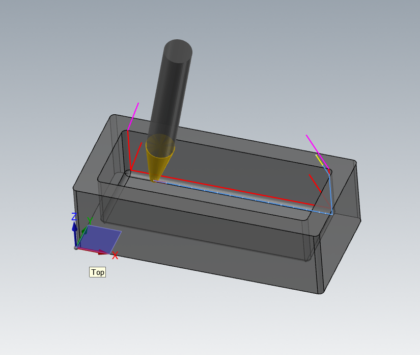
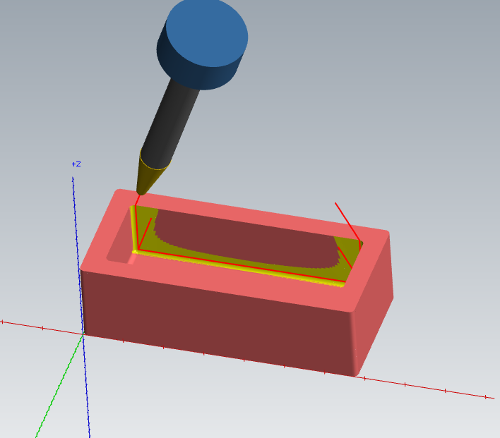
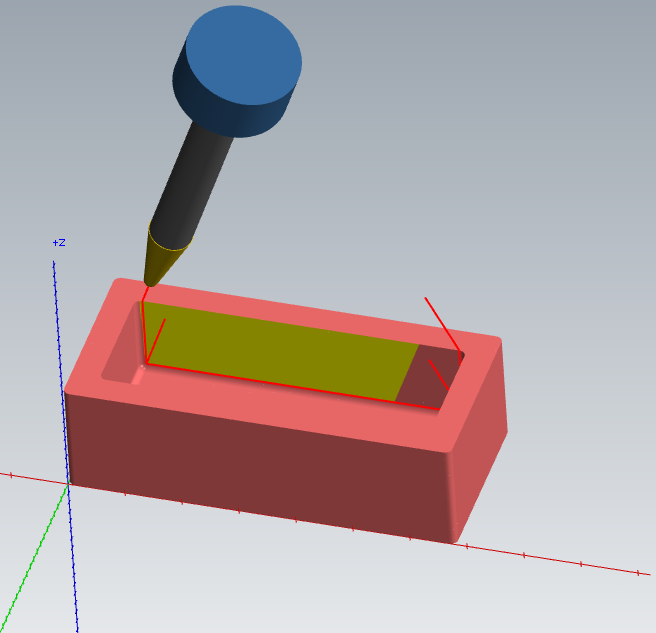
Tool path is new swarf, only one pass. Collision checking on. You can see in the picture the gouge in the wall corner. When stepping through verify I can see the gouge happening but the tool is where is should be, in other words, the tool is cutting beyond its boundary. I am certain the gouge is happening in this path. In back plot the tool is not gouging. Have you ever seen this? I could post the file on Monday when I get back to work. I took these screen shots yesterday for this post. No collision warnings are called. Thanks, Steve Austin
-
I have found that using a Bull end mill, say 1/2 with a .125 radius leaves a much better finish than a ball. You can get a wider step over too if cutting in the right direction. Of coarse than may not work in tight cavities but it would on the flatter areas and the slopes.
-
When in Verify, go to File, Options, be sure "Always use 5 Axis Engine is Checked", and then save configuration. This might be your problem.
-
Why should even have to be covered. Learn to use the software and these things will become self evident. I learned how to do this on my own.
-
OKUMA 5X TRUNNION G169 TCPC GIVING WEIRD NUMBER
lowcountrycamo replied to lowcountrycamo's topic in Industrial Forum
I am getting better motion now accept the tool is dwelling when the B and C start and stop. While the rotaries are moving the motion looks good but when the code transitions to and from only xyz their is a distinct pause. Almost like it is waiting for clamp and unclamp, but they are not in the code. I have tried lowering and raising the tolerance and angle step and that does not help. Greg, I have seen several of your videos I don't see this dwell in your programs. I downloaded your files and noted that you are using feed in Unit/Min in the Control file. No inverse. Are you also using TCPC? Could this dwell be coming from and In Position Check? These are 1 year old twin machines. I have searched the manuals but cannot find anything. I know Fanuc much better than OSP. Thank you, Steve Austin -
OKUMA 5X TRUNNION G169 TCPC GIVING WEIRD NUMBER
lowcountrycamo replied to lowcountrycamo's topic in Industrial Forum
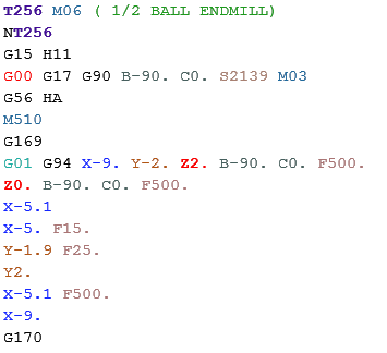
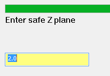
So I am beginning to understand what it going on. I did a simple 5x curve and looked at the output compared to the geometry dimensions in top plane. The path is output as if it were cut from the top plane. I had a 4" incremental clearance and z5." cut. The initial z2. position comes from a "safe Z" dialogue box. I believe this z position is where the machine first moves in x. At work earlier today I had a z12. in the dialogue box and the machine was going to x12. first and then approaching from the right side.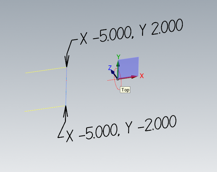
-
We have an Okuma mu4000 5x trunnion and post from Impostablilty. Love the post. We recently started using G169 TCPC so we could get away from inverse time G93. The tool path runs as it should but approaches from the side instead of from Z. In one case the trunnion was over at B-90. C0. The position should have been about X8.xxx , Z2.xxx but output X2.xxx and Z8.xxx. It did run well other than the lateral approach but this worries me, as I don't understand what is happening. I will contact my reseller if I need to but though I might get an easy answer here first. Thanks very much, Steve Austin
-
Driven point should be on the tool tip or gage length in tool manager?
-
This is not the question you asked but could just copy the post, edit the clamp codes in the string list and have each machine def use its own copied post. Sorry if this defeats your intent.
-
advise on tool axis control - Parallel
lowcountrycamo replied to lowcountrycamo's topic in Industrial Forum
I am trying to run the tool up and down the walls to get the rad there. I might end up with a .250 ball but looking for a better solution. -
We do aerospace parts. A family of parts I am about to do have .125 wall and floor radius. I am looking for a path that will clean up both in one smooth pass with a 10 degree tapered end mill. I found that Parallel will get close but the tool axis does not stay true to the wall the entire path. I am using lines at both ends. The angle is correct at the corners but when transitioning between the 2 it pulls off due to geometric laws. I found that if I did half of the wall at once with 1 axis line it does clean up. I attached a file. Can anyone think or a better way to do this? Thank you, Steve A fillet and wall clean up.mcam
-
How to create negative impression of machined stock model?
lowcountrycamo replied to Corp6's topic in Industrial Forum
You can import Stl in Solis works and export as stp -
What of tool number showed up again 3 tools later? That I would really like.
-
Mastercam's System Resource Utilization
lowcountrycamo replied to ad1187's topic in Industrial Forum
Most of the crunching is done by the gpu correct? Is that an industrial card like quadro? There is a difference. If it is, excuse me -
Linear Moves Galore! How to STOP!
lowcountrycamo replied to Kampfzentrum's topic in Industrial Forum
Is your chain made of several line segments? Is he using "Adjust start length" on the lead in out page? -
CIRCLE DIAMETER PARAMETER
lowcountrycamo replied to PcRobotic's topic in Post Processor Development Forum
Not post version but MP Doc where you found the parameter. -
I can't believe I need to ask this.... Manual tool change
lowcountrycamo replied to jaydenn's topic in Industrial Forum
I added this at psof pbld, n$, "G90 G00 Z15.", e$ pbld, n$, "G00 Y-10.", e$ pbld, n$,"M00", "(LOAD", *t$, ")", e$ pcan ptoolcomment pbld, n$,"("*t$, sm06, ")"e$ => N3 G90 G00 Z15. N4 G00 Y-10. N5 M00 (LOAD T7 ) ( 7/32 DRILL .2187 OSG .5LOC .7CLR | TOOL - 7 | DIA. OFF. - 7 | LEN. - 7 | TOOL DIA. - .2187 ) N6 ( T7 M6 ) and this at pretract$ pbld, n$, sccomp, *sm05, psub_end_mny, e$ pbld, n$, "G90 G00 Z15.", e$ #sgabsinc, sgcode, *sg28ref, "Z0.", scoolant, e$ pbld, n$, "G00 Y-10.", e$ and this at ptlchg$ pbld, n$,"M00", "(LOAD", *t$, ")", e$ pcan ptoolcomment result = newfs(15, feed) #Reset the output format for 'feed' pbld, n$,"("*t$, sm06, ")"e$ => N16 G90 G00 Z15. N17 G00 Y-10. ( WEAR COMP FOR THIS TOOL D3 = .000 ) N18 M00 (LOAD T3 ) ( 1/4 FLAT ENDMILL .75LOC 1.CLR | TOOL - 3 | DIA. OFF. - 3 | LEN. - 3 | TOOL DIA. - .25 ) N19 ( T3 M6 ) Too easy thanks to this forum and Colin's post classes. Machines without tool changers are more rare than 5x machines. Therefore post support is not a freebe. -
Work offset force to appear at ...
lowcountrycamo replied to PcRobotic's topic in Post Processor Development Forum
If you put an * before such as *g_wcs is forces output. I tried *g_wcs and it output g54 at null toolchange. I tried *pwcs and it did nothing. -
10030 is the parameter number for feeerate. Works nicely. Now that I learned out to do this I can customize it even more so. Thanks Colin, with 1 "L"! Steve Austin
