


lowcountrycamo
-
Posts
247 -
Joined
-
Last visited
-
Days Won
2
Content Type
Profiles
Forums
Downloads
Store
eMastercam Wiki
Blogs
Gallery
Events
Everything posted by lowcountrycamo
-

Posting compensation offsets in post
lowcountrycamo replied to Grimes's topic in Post Processor Development Forum
Do you want it at the top or at the tool change? This would work at tool changes for wear comp: if comp_type = 2, "(", tloffno$ , "=.000)", e$ This would post the d# at the toolchange. comp_type 2 is wear comp which is the only kind I use so I might incorporate this into my posts. You would need this in psof$, ptlchg$. This will output the D# of what ever tool is up. -
Thank you Collin. I learned several things from this sort post. I think I can make this happen.
-
I just started using Mill.set reports which I love. However, I noticed today that upon the 1st null toolchange the feedrate will be copied from the 1st tool. After the 2nd null toolchange the feedrate is correct. This error repeatable across different tools I tried. I have attached my Mill.set post file. I would love to get this squared away as I really want to use this report for self checking and prove out. Thanks, Steve A Here is what it posted: CUSTOMIZABLE MILL SETUP SHEET - MILL.SET ========================================= PROGRAM NAME = 1159CM50121-15 DATE PROCESSED = MAY. 23 2018 TIME = 3:30 PM MACHINE NAME = OKUMA 3X 650 -------------------------------------------------------------- OPERATION TYPE = CONTOUR T20 - 1/2 ENDMILL 7 FLUTE 0.125 RAD 1.75LOC 2.CLR USE 5.GAGE SHRINK HOLDER ***** SPINDLE ***** = 2292 ***** FEEDRATE ***** = 85. <-----------------------------------------correct CUTTER COMP. (COMPUTER) = LEFT STOCK TO LEAVE (XY)= -.125 STOCK TO LEAVE (Z) = .01 FEEDRATES: MAX = 85. MIN = 85. MAX_Z = +8.0000 MIN_Z = +5.0468 RAPID TIME = 2 MINUTES, 25.96 SECONDS FEED TIME = 21 MINUTES, 42.47 SECONDS OPERATION TIME = 24 MINUTES, 8.43 SECONDS -------------------------------------------------------------- OPERATION TYPE = 2-D HARDMILL MACHINING/PEEL MILL T20 - 1/2 ENDMILL 7 FLUTE 0.125 RAD 1.75LOC 2.CLR USE 5.GAGE SHRINK HOLDER ***** SPINDLE ***** = 2292 ***** FEEDRATE ***** = 85. <-----------------------------------------should be 81.87 CUTTER COMP. (COMPUTER) = LEFT STOCK TO LEAVE (XY)= 0. STOCK TO LEAVE (Z) = .125 FEEDRATES: MAX = 500. MIN = 50. MAX_Z = +8.0000 MIN_Z = +3.3773 RAPID TIME = 1 MINUTE, 45.79 SECONDS FEED TIME = 9 MINUTES, 12.42 SECONDS OPERATION TIME = 10 MINUTES, 58.22 SECONDS -------------------------------------------------------------- OPERATION TYPE = 2-D HARDMILL MACHINING/PEEL MILL T20 - 1/2 ENDMILL 7 FLUTE 0.125 RAD 1.75LOC 2.CLR USE 5.GAGE SHRINK HOLDER ***** SPINDLE ***** = 2292 ***** FEEDRATE ***** = 81.87 <-----------------------------------------correct CUTTER COMP. (COMPUTER) = LEFT STOCK TO LEAVE (XY)= .01 STOCK TO LEAVE (Z) = .125 FEEDRATES: MAX = 500. MIN = 50. MAX_Z = +8.0000 MIN_Z = +3.3773 RAPID TIME = 1 MINUTE, 45.59 SECONDS FEED TIME = 16 MINUTES, 55.28 SECONDS OPERATION TIME = 18 MINUTES, 40.87 SECONDS ============================================================== PROGRAM TOTALS (3 TOOLS): FEEDRATES: MAX = 500. MIN = 50. MAX_Z = +8.0000 MIN_Z = +3.3773 TOTAL RAPID TIME = 5 MINUTES, 57.34 SECONDS TOTAL FEED TIME = 47 MINUTES, 50.18 SECONDS CYCLE TIME: 54 MINUTES, 5.52 SECONDS MILL.SET
-
I have net hasp but mcam say need activation code???
lowcountrycamo replied to lowcountrycamo's topic in Industrial Forum
Here is the error
-
I have a nethasp that seems to be up to date. This morning mcam say I need activation code. What it happening. I am lock out.

-
I have received that twice this week. 3 parts programed and done today, "sorry I forgot to tell you last week."
-
Am I allowed so say eapprentice.net?
-
When I use dynamic 2d to mill (face) rectangular shapes from outside I get tool breakage near the center when the tool takes the corner. I attached a pic of what I am referring to. Has anyone ever come up with a way to avoid this? I wish I could make the tool go past before making the turn, when approaching the center of the path.

-
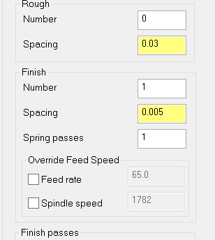
For close tol. I like a small depth finish pass as it prevents the tool from deflecting thus cutting slightly deeper. However, in most cases I try to cut to the first depth.
-
Never mind, I found it. I was the lead in/out override. I must have accidentally clicked it as I have never used that before. Sorry for the following posts. Edit: Ha, Ha, I must have been typing this just as JeffD found my error. I feel like I learned a couple thing today guys. Thank you very much!
-
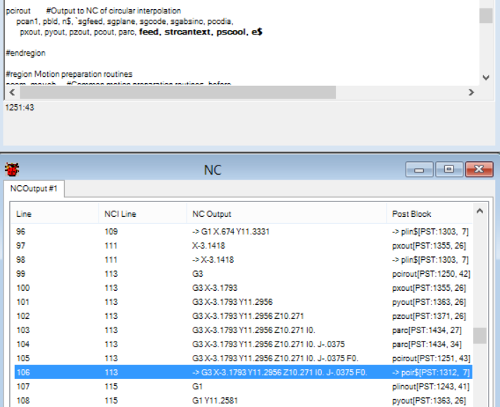
So I ran debug and although I don't understand that much about that software I think I found where the G03 feed comes from. Is this the place? pcirout #Output to NC of circular interpolation pcan1, pbld, n$, `sgfeed, sgplane, sgcode, sgabsinc, pccdia, pxout, pyout, pzout, pcout, parc, feed, strcantext, pscool, e$ when I click the suspect block in Debugg, this NCI code is highlighted 0 0 -3.17932258 11.29560032 -3.14182258 11.29560032 10.271001 0. 0 0
-
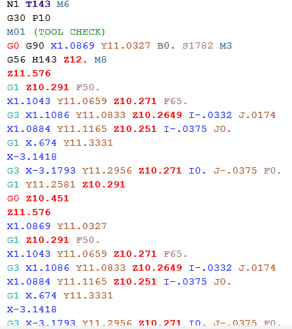
So I checked and I had no f0. input that I could find. Here is the code. Only on G03. Is there anywhere else this could be coming from? I am going to see what debug will show.?
-
Hi, I recently modified a fanuc 4x post for okuma osp with info I found on this site. Changed g43 to g56, g54 to g15 and such. I am getting a f0. on only one contour just on a g03 block. I made a ztogo. Could use some help on this. Thanks. Steve F0 PROBLEM.ZIP
-
We have 3 Horizontal Aluminum machines. They might be similar to the HPS-120B/5, or just alike. 20K spindle and never go above 16000 because spindles only last about 1year at that speed. We run big parts at 300ipm for 20hrs daily. We have some that have lasted weeks. Although we get 6months warranty. Loose 10 days for each spindle. This is the older design so maybe they have improved. For all I know that is normal for machines like this and a similar Makino Mag is much more$. I like the SNK other than that. They can make a 1000 lbs of chips in a shift.
-
Generic 5x post and g43.4
lowcountrycamo replied to lowcountrycamo's topic in Post Processor Development Forum
I will look. Thanks Collin. -
Generic 5x post and g43.4
lowcountrycamo replied to lowcountrycamo's topic in Post Processor Development Forum
-
First, I want to credit Collins' live classes and the Eapprentice videos for my post education. Lots of knowledge there! No one at work asked me to do this, I am trying to make myself more valuable in the future. I have been working on a post for a big Horizontal SNK AC Head/Head mill using the Generic 5x post. Fortunately, I have Vericut at work with a SNK project all setup that our Catia programmers use. They have a pretty good SNK post. They use G43.4. At work yesterday I was testing my post and I have the sim cutting correctly, but still lack G43.4. I manually inserted G43.4 in the program. I could see no difference in the location of an angled cut with G43 or G43.4. Is the sim not set up right? I made a cut with A-45 at Y.0. I would think with G43 the cut would have bee 10" or so off position. It was not. shift_z_pvt :2 tool tip programming - correct? Also, I did not see any G43.4 in the 5x post. Can I just modify the out put or is there something else that should happen that I don't understand. Thanks
-
I have an aircraft part that has a slight curve. The part is .1 thick, 55" long, and has about .15 dip in the center. We do we were hoping to cut it out of flat plat. There is another part that is attached to it that will give it the curve. I have seen surface flat chook but that untrims the surface so that won't work. Any ideas? Thanks steve
-
I have also received that error in 2018 only. I seems just some files some of the time. If I check no my wire frame will not import into verify. If I check yes several times it will. Other than that it has caused me no real issues.
-
This doesn't help the OP but I moved ptoolcomment after pcomment so a Manual Data Input would not come before tool callout. With a large Manual Data the code can look confusing to the operators.
-
This is very clever. For this to work you must program from the center of the ball. I posted it out and it looks like you would have to subtract the radius of the ball from the tool offset. Is that correct?
-
Maybe not in your case but on angled walls the path may look like it Is not going far enough because the tool is cutting further out from the toolpath line.
-
Is it really that bad? Why have the option at all then?
-
I have been trying for a couple weeks to learn VTL programming. After reading old posts here and following there advise I just got more confused. First, do I draw geometry before I call up a VTL or after? After calling up what View, WCS, T, and C should I be in? Should the T anc C be =? When I bring in a VTL sometimes the software selects planes automatically, sometimes it just remains in the planes I am already in. Should I be cutting on the right side of the screen or left? Should the tool insert be facing me or away? Am I looking at the part as if I was standing in front of the machine as a horizontal lathe? The H Lathe was easy for me to get. However, I cannot seem to find any good tutorials on the VTL I program multi axis mills everyday but cannot get this. I feel really dumb right now. Thanks, Steve A
-
I got to work yesterday and my right click menu had reverted back to the generic state.
