


cncappsjames
-
Posts
1,209 -
Joined
-
Last visited
-
Days Won
85
Content Type
Profiles
Forums
Downloads
Store
eMastercam Wiki
Blogs
Gallery
Events
Everything posted by cncappsjames
-
I'm of the opinion that if you buy that kind of machine but can't afford to make it do what it was designed to do, you shouldn't even be getting in the game in the first place. May as well put radials on an F1. Seriously.
-
Buying a 5-Axis machine without TWP, TCP, WSEC... all in an effort to save a few grand... I just don't get it.
-
One key thing one needs to understand about Productivity Plus is it is skip signal based and not cycle based. Meaning you program a 4 point bore in Prod. Plus, you're not going to get a position to the center of the bore then the G65P9814... bore cycle. You're going to 4 individual measurement points and a bunch of protected moves in between. Then if you wanted to get the #135-#149 variable data based on the cycle, you won't have that data available. Food for thought.
-

5ax Mill Indexing
cncappsjames replied to [email protected]'s topic in Machining, Tools, Cutting & Probing
@[email protected] according to EIA 267-C standard as I understand it, that is opposite. If standing in front of the operator door, A- should tilt toward you and A+ shoudl tilt away from you. Any chance you can get the builder/dealer to switch that? -
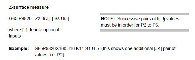
Like @Leon82 mentioned, the G65P9820 stock cycle could do it automatically. It's listed in the "Additional Cycles" section of your manual.
-
Forgot about that one...
-
That would take some MACRO work. Me, I'd hit a corner write to a work offset (G54 for example), take the Z from that work offset (#5223) and write it off somewhere else (#191). Rinse and repeat 3 more times (#192, #193, and #194). Then after you find the one you want write a MACRO that makes the one you want your work Offset Value (say #193 is the winner) #5223=#193 Maybe not elegant, but it'll get the job done... on a FANUC.
-
Here's where things get a little confusing for those outside the business. Some builders use the standard set of AICC parameters and other builders use a different group of parameters for servo tuning. "Most" use the standard group or standard plus R (G05.1Q1 R0 through G05.1Q1 R10). Matsuura uses those plus about 75 more. Makes for interesting testing for sure. Thankfully, they come from the factory in good shape. All but the most cycle time conscious are pretty happy with the end result. Some will point out some inefficiency somewhere, and it costs an extra second... yet the machine sits idle for 50% of the day... Fortunately, over the years I've learned where I can shave time and still maintain the integrity of the machine. That's the key. A group of us was discussing velocity and machining and the effects high G acc/dec on the life of the machine tool, life of the sheet metal, etc... It was a fun discussion. If you want to sacrifice accuracy and machine lifespan, we can do a lot. We come standard with 600 and go to 1,000 for certain applications. Anymore, with the types of toolpaths CAM systems are generating, 600 is really BARE MINIMUM ON A 5-Axis. Think about it, on a finishing path, you're going to want between 200µm and 300µm point spacing, and a tool path tolerance between 20µm and 30µm. That's A LOT of points along a 25mm stretch, you need to give the control some room to breathe. IMHO of course.
-
@PAnderson we had a customer that wanted some reporting capability but didn't feel the need to get the Renishaw package as the Matsuura package was meeting his needs so we added this to the bottom of the check so he could so some tracking. @Leon82, if you're running Matsuura's eZ-5, drop this in before your M30 after the cycle runs and you can get this report. This would be for an A/C Kinematic VMC. Make sure you have a device in your active I/O (i.e. USB, CF, etc...) #900=[#870-#880] #901=[#871-#881] #902=[#872-#882] #903=[#873-#883] #905=[#875-#885] POPEN N700DPRNT[NOTE*ALL*UNITS*IN*MM*BELOW] N800DPRNT[PARAMETER*19700*X*ERROR*IS*#900[13]] N801DPRNT[PARAMETER*19701*Y*ERROR*IS*#901[13]] N802DPRNT[PARAMETER*19702*Z*ERROR*IS*#902[13]] N804DPRNT[PARAMETER*19704*1/2*OFFSET*Y*ERROR*IS*#904[13]] N805DPRNT[PARAMETER*19705*1/2*OFFSET*Z*ERROR*IS*#905[13]] N807DPRNT[*] N9000DPRNT[CORRECTIONS*TO*MAKE*NOTED*BELOW] N9002DPRNT[IF**A**ARGUMENT*IS*A1*THE*FOLLOWING*CHANGES*WILL*BE*MADE] N19700DPRNT[PARAMETER*19700*WILL*BE*CHANGED*FROM*#880[33]] DPRNT[*TO*#870[33]] N19701DPRNT[PARAMETER*19701*WILL*BE*CHANGED*FROM*#881[33]] DPRNT[*TO*#871[33]] N19702DPRNT[PARAMETER*19702*WILL*BE*CHANGED*FROM*#882[33]] DPRNT[*TO*#872[33]] N19703DPRNT[PARAMETER*19703*NOT*APPLICABLE*TO*A/C*KINEMATIC*MACHINES] N19704DPRNT[PARAMETER*19704*WILL*BE*CHANGED*FROM*#884[13]] DPRNT[*TO*#874[33]] N19705DPRNT[PARAMETER*19705*WILL*BE*CHANGED*FROM*#885[23]] DPRNT[*TO*#875[33]] PCLOS M30 % HTH
-
Especially in your market. On the high-end side of the business it's not quite as bad, but it's still there to a certain extent. Annnnnnnnnd no matter how good the probing packages are, they still won;t get you down to the single digit micron level. Probing is "almost" a static endeavor. I mean, sure the axes are moving under servo load, but all the dynamic things that go on during the metal removal process are not present (i.e. high velocity motion, dynamic cutting forces, spindle deflection, etc...) so it'll only get you so close. You've got to cut a part to get the rest of the way there. IMHO of course.
-
@PAnderson, if we want to get down to the nitty gritty, you are correct. Servo tuning should take place for each different part run. Very impractical in the real world. In my experience, the AICC parameters are set so that a max weight scenario will produce a good part, or won't give you servo overload conditions. In all honesty, this is the safest approach. As far as machine geometry... yeah. CRITICAL to check squareness, parallelism, perpendicularity, etc... BEFORE making any changes to the kinematic parameters. Renishaw has a probing package available; Axi-Set. It comes with a sphere mounted to a mag-base. The thing about it is you MUST run it while the machine and axes are at operating temp. If they are not, there could be mis-match issues. There's definitely more than meets the eye when it comes to this stuff without a doubt. Not all customers appreciate the time that goes into integrating and developing all the systems (mechanical, software, options, etc...) to help them do complicated things more easily. But like you, we just do the best we can with what's available.
-
Thanks for the kind words.
-
I remember that situation. The programmer kept saying it was this, but really it was that. He was thinking 3-Axis realm, and I had to explain and prove that no, it's a 5-Axis realm thing and here's why... Unfortunately, I don't think I was ever able to explain it to him in a way that made sense to him, but, the bottom line is it made good parts after the adjustment so... there is that. Note to self; work on communication skills.
-
Same here.
-
That's not a simple X or Y answer because often, control options are installed in the field by either the Builder/Dealer and/or FANUC. Doesn't happen very often for us because we get them configured properly from the factory, then we change around 16 parameters that aid customer convenience and capability when we do training. I know how to do some servo tuning and have a basic working knowledge of FANUC Servo Guide though. I could get better at it and it's on my list of skills to be mastered. IMHO, an AE should know how to do it though because of your situation. It happens WAY too often IMHO. Builders could save themselves some grief if they handled it at the factory, but then again, I don't think builders should let improperly optioned machines out in the wild like they do on a regular basis. Some builders are worse than others. This totally unavoidable situation gives the control a bad name unfortunately when in all reality, it's 100% the builder. We sell Matsuuras on the West Coast. Matsuura USA doesn't even import a machine without the correct option package installed. Why? Because it's just better that way. Is it more expensive? Perhaps. However, you factor in time wasted, perhaps some parts get scrapped, time and expense of field installing options, fine tuning options, time, energy, etc... you're way better off just doing it right from the get go.
-
ALL modern (mid-90's era and newer) CNC machines should be running some sort of look-ahead mode (G05, G05.1, G08, COMPCAD, etc...) on any sort of toolpath that is not a canned cycle. Period. End of story. There's always been varying opinions on this, however, the bottom line is of you want performance AND accuracy, you're running the correct High Speed Mode for the task at hand. If you're not, you're running slow, or you're running scrap. There's only a few AE's that know anything about FANUC AICC tuning in SoCal. In all honesty, you're probably going to be talking to https://okkcorp.com/support/ in order to get any sort of high level support. Just for curiosity's sake I was wondering how long we've been beating this high speed look-ahead horse, and it looks like since about 2004. That is a LONG time. I know I've been training people to use the high speed modes installed on their machines since around 1997-ish. The fact we're STILL having this discussion does not show well for the Applications Engineers for their respective builders and dealers. When are we going to collectively get our customers adequately trained?
-
Camplete linearized my surface flowlinr arcs
cncappsjames replied to Leon82's topic in Machining, Tools, Cutting & Probing
The cell phone today, is yesteryear's scratchpad and notebook. I get it. People abuse the tool so nobody gets to use it. Typical. People/Companies are too lazy to create acceptable use policies for devices so they just kill it for everyone. Stupid. As a law abiding gun owner and CCW holder, I get blamed/regulated/penalized for every criminal/unlawful use of a firearm. It's bull$#!+!!! My phone is a MASSIVE toolbox that would require me to have a Semi-Truck to store all the manuals and information I use on a regular basis. -
look ahead parmeter on a fanuc 31i control
cncappsjames replied to kenfromlodi's topic in Industrial Forum
Some old topics have been resurrecting lately. I wonder, do these topics show up in Google searches and that's what drives it? -
Proper program format for probing; G5.1Q0 G54(Put tilt and rotary addresses and angles ONLY here) G68.2X0Y0Z0I...J...K... G53.1 G43H... Blah, blah, blah Probe for X, Y, and Z error. Capturing values and writing them to alternate variables that don't get overwritten. Then probe for A error, B error, and C error. Store those off as well. Then write the errors to the WSEC offset variables. The lower case addresses (x, y, z, a, b, c) in the offset table are the error amounts. The upper case values are the MACHINE angles of the tilt and rotary where the measurement was taken. Turn off the probe. Continue machining. If any of that you don't understand, I'd reccommend getting in touch with the company that sold you the machine and have their Application Engineer come and go over the process with you. Training for this via forum isn't the best way to approach it. There are machine parameters involved, there is Custom MACRO B involved, there is order of probing hits involved, etc... all things that are extraordinarily hard to do remotely. I know, I do this for a living. First and foremost, your machine HAS to be set up and configured properly. If that's not squared away first then this is all just a mental exercise. JM2CFWIW
-
look ahead parmeter on a fanuc 31i control
cncappsjames replied to kenfromlodi's topic in Industrial Forum
Those M60-M62 are related to pallet changes. M06... y'all know what those are for. In the empty ones, I'd create a new M-Code program in the library... O9020-O9029 Then find the open corresponding 6080-6089 parameter. % O9020 (FOR EXAMPLE - M900) G04X.1 M99 % #6080=900 #3415=900 Then before your MACRO calls, command M900 and it should stop buffering. Just some basic ideas... Hope that helps. -
look ahead parmeter on a fanuc 31i control
cncappsjames replied to kenfromlodi's topic in Industrial Forum
Parameters #3411 to #3420 specify which m-codes prevent buffering. -
I don't think so. It appears he's trying to use G68.2 like it is WSEC. That'll never work.
-
Do they make a thinner pallet for the mam100?
cncappsjames replied to Leon82's topic in Machining, Tools, Cutting & Probing
Mitsubishi and single pallet only on the Kitty. They are new kids on the block in the 5-Axis realm. Like they are still in diapers and Matsuura is the robust grandpa watching the kiddos on the playground. -
FRUSTRATED!!! help
cncappsjames replied to [email protected]'s topic in Machining, Tools, Cutting & Probing
Those are splines... you're rarely ever going to have success extruding that. If you absolutely have to have a shaded image, go to Surfaces, pick Draft and chain your shape and the length is how tall you want it. Do that. Transform copy the chain up the thickness you want, then create flat boundary surfaces on the top and bottom. Now, you should be able to go to solids and create a solid body from surfaces and select the walls, floor and ceiling and it'll work then. Post-IT Housing III - Draft - Solids From Surfaces.zip -
Camplete linearized my surface flowlinr arcs
cncappsjames replied to Leon82's topic in Machining, Tools, Cutting & Probing
Ok, in the File IO Options in Tools, Options... go to the Mastercam in the pull-down and check the following; NCI - Arc Radius Maximum (0 for no maximum - mine is set to 0) NCI - Arc Radius Tolerance - (mine is set to 0) NCI - Circular Interpolation Move - Add Linear Move For Small Arcs (unchecked) NCI - Circular Interpolation Move Tolerance (mine is set to .0001 in) NCI - Convert Arcs To Points When Reading Rotary Axis Angle From Tool View (mine is unchecked)

