


cncappsjames
-
Posts
1,210 -
Joined
-
Last visited
-
Days Won
85
Content Type
Profiles
Forums
Downloads
Store
eMastercam Wiki
Blogs
Gallery
Events
Everything posted by cncappsjames
-
I think graphical toolpath editing would be a better next step.
-

5 Axis Gantry Programming
cncappsjames replied to mayu's topic in Machining, Tools, Cutting & Probing
I'm never the smartest guy in the room so I have to rely on brute force to be my superpower. -
Should be an interesting ride... I wonder if Vericut will decide to jump into the Post Processing pool now?
-
5 Axis Gantry Programming
cncappsjames replied to mayu's topic in Machining, Tools, Cutting & Probing
That's a VERY valid AND fair criticism. On the Applications Engineer side, you've got every skill set from "...I know how to turn on a machine and do and teach basic functions..." up through I can take a dysfunctional control , make it perform as expected or better, AND teach someone else how to do it" and everything in between. The VAST majority being in the 1st camp. I found out early on when I worked for Mori there's two basic levels of understanding regarding CNC machines. 1) The "Operator" Level; meaning I understand the control and machine from an operator, programmer and setup standpoint and 2) The Engineer Level; meaning, I have a problem with a function on my machine and I know how to troubleshoot and solve the problem. My personal goal has always been to be on the latter side as opposed to the former side. Me, I'm still learning every day so... at least I'm on the path . I feel like I have a long way to go to be THE MAN. The reality for that level of knowledge and expertise is that it has to kind of be a personal mission type deal. IOW, when a customer or a competitor says "... you can't do that...", or such and such "... is impossible...", you have to want to be the "... oh, yeah... watch this..." kind of guy. There really are FEW that are willing to put in the time and effort to be THAT guy. They are your 6 figure guys. The top end of the talent pool if you will. They are few and far between unfortunately. Because they are so few and far between, it often makes machine tools look unnecessarily bad. JM2CFWIW -
The easiest thing to do then would be to open up one of his projects and see what he did, what post he used, etc...
-
Pay less attention to that stuff and more attention running parts. You'll get more done. JM2CFWIW
-
5 Axis Gantry Programming
cncappsjames replied to mayu's topic in Machining, Tools, Cutting & Probing
Understanding the business the way I do, believe it or not, there are legitimate reasons that could be the case where two back to back machines could be configured differently. MC1 is a factory pre-order, configured per the sales order. MC2 on the line was set to be a "stock" machine. Configured in a basic manner. Happens all the time. Dealers and builders shift machine orders all the time for a variety of reasons. Now, "should" a machine tool builder configure all 5-Axis machines the same? That is a legitimate question. A LOT of questions would need to be answered first. JM2CFWIW -
5 Axis Gantry Programming
cncappsjames replied to mayu's topic in Machining, Tools, Cutting & Probing
There's actually a few parameters that dictate that behavior in various conditions. -
5 Axis Gantry Programming
cncappsjames replied to mayu's topic in Machining, Tools, Cutting & Probing
I use it strictly for a safe pre-position move. You are absolutely correct in the claim of it not being required. This would fall under the category of a "preference". -
5 Axis Gantry Programming
cncappsjames replied to mayu's topic in Machining, Tools, Cutting & Probing
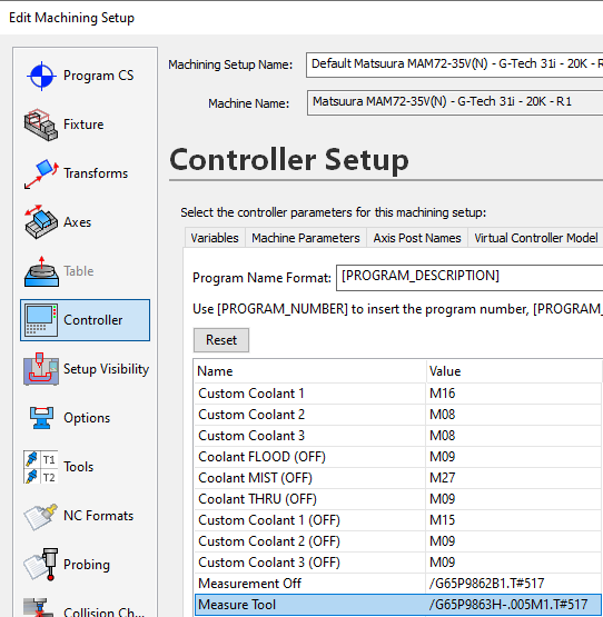
TWP is activated independently and before you activate TCP. Usually you do not run them together. TWP is not a rotary type function. It is a 3+2 type function. TCP is the rotary type function. On a FANUC, you would activate things in the following manner; N5T5M06(1/32 Stub LOC Ball E/M - BBT40-MEGAER16-90NL) G49G53Z0.0T6 M08 G131F1(ACTIVATE HIGH SPEED LOOK AHEAD FOR MATSUURA) (Flow ISO-TC39SC2-N2185 Feature - Side 1) S20000M03 M132(UNCLAMP A AND C AXES) G00G90G54A-29.755C-147.24 G54.4 P1(ACTIVATE WSEC) G68.2 X0.0 Y0.0 Z0.0 I-147.24 J-29.755 K0.0(ACTIVATE TWP) G53.1(ACTIVATE SPINDLE DIRECTION) X0.5398Y0.4636 G69(CANCEL TWP) G43.4Z0.5H#517(ACTIVATE TWP) X0.0994Y-1.152Z0.8547 G130(CANCEL HIGH SPEED MODE) G00G90G49(CANCEL TCP) G53Z0.0(MACHINE HOME Z-AXIS) G54.4 P0(CANCEL WSEC) -
Definitely a HIGH production machine. I don't see a whole lot of that kind of work. Maybe 1-2 a year.
-
Only true if you haven't run the vector calibration cycle and if you don't use vectored probing cycles. We always do the vector calibration and use the vector cycles when appropriate.
-
My guess is the latter. Everyone wants the Easy Button. Machine Tool probing has lagged behind CMM measurement honestly. Hoping they will up that game. Productivity+..... meh. IMHO it's not as powerful as Inspection Plus. Productivity+ is just capturing skip signal trigger points and doing something. Inspection Plus OTOH every probe cycle gives you the following info (or at least info related to the cycle in question); #135 X Position #136 Y Position #137 Z Position #138 Feature Size #139 Surface Angle #140 X Error #141 Y Error #142 Z Error #143 Size Error #144 Angle Error #145 True Position Error #146 Metal #147 Direction Indication #148 Out Of Tolerance Flag (1~7) #149 Probe Error Flag (0~2) Inspection plus can a little more laborious as you're manually writing the cycles, but the reality is there are only like 13 cyles in total with 6 being used probably 90% of the time, and 3 of those 6 are probably used 90% of the 90%. Single Surface, Bore/Boss and Web Pocket being the most commonly used cycles. Call the probe to the spindle Activate your work offset and tool length offset You turn on the probe You move it into measurement position using the protected cycle You measure the feature You move it away using the protected move You turn off the probe You send Z home. That's your cycle. Obviously they can get infinitely more complicated based on what the desired goal is; I've done simple XYZ offset setting up to full blown part inspections with formatted DPRINT output for SPC purposes and a lot in between. I've just never really been that impressed with Productivity+. Guess I'm just old school that way.
-
@Leon82, do you have to documentation for the function?
-
I'd be willing to bet Video Card issues is the single most plentiful issue since the forum got started 20 years ago. No joke. @Velerona if you want to roll the dice, go right ahead, however, when you have issues, you'll be promptly told "we told you so". You'll get offended, then probably leave. This forum membership is littered with hundreds if not thousands of users that were warned. No exaggeration. They didn't heed the advise and didn't like getting scolded for it, then REALLY didn't like getting told there was no fix for their issue and reminded they were warned. Please, we beg of you, do yourself a favor and spend a few hundred more bucks and get a CAD/CAM card. No need to spend thousands, but be smart. JM2CFWIW
-
Looks liek there was a problem in my download the 1st time. Sorry for the confusion. I second Ron's opinion. That part will move. There's no way to maintain clocking. If there were, "I" would set X, Y, Z at the center of the boss and top of the fixture. Also, that fixture, I'd sink further down in the vise so I could get some clampng force on it. This would give give you the most rigidity possible. The ellipse within the concave is going to be a problem. You need a radius on those feature intersections otherwise you'll have a REALLY hard time not gouging something. (probably the wall). JM2CFWIW
-
Disasters are ALWAYS opportunities. It's all in how you look at things. 1) Not necessarily. This depends entirely on what options your machine has AND what functions your post processor supports. 2) You need the stackup when doing collision checking. 3) Set your work cordinates based on the features of your machine and post processor. All the machines I work on have Tilted Work Plane (G68.2), TCP (G43.4) and WESC (G54.4). So, I set my work offset "usually" on the part datums, Center of rotation info is in the CNC's control in parameters so I don't really "need" to know it, or have it anywherein my CAM system. I was unable to open your file in Mastercam 2021...
-
For me, it's 100% a case by case basis on Solid Chain vs. Wireframe Chain. I like new tools. I like old tools. A good programmer can discern which tool will work best for each feature. JM2CFWIW
-
Limit C axis between 0 and 360
cncappsjames replied to [L]'s topic in Machining, Tools, Cutting & Probing
You talking about the code? -
Possible to speed up Fanuc control?
cncappsjames replied to Tinger's topic in Machining, Tools, Cutting & Probing

-
Possible to speed up Fanuc control?
cncappsjames replied to Tinger's topic in Machining, Tools, Cutting & Probing
M98 Q is like a GOTO almost. It has to internally scan through the program. This is the slowest method. I'd have 1 program, run M198. THere's no processing penalty that way. JM2CFWIW -
Some camplete tricks i worked on
cncappsjames replied to Leon82's topic in Machining, Tools, Cutting & Probing
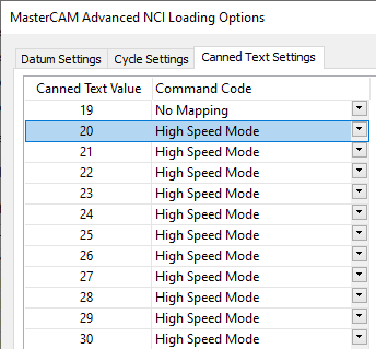
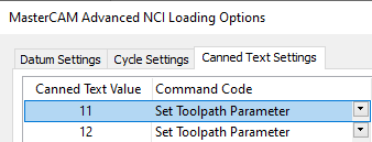
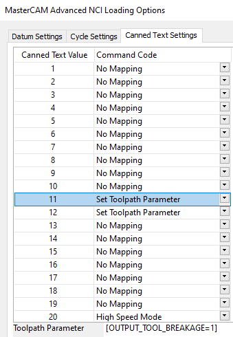
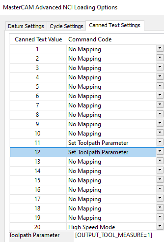
I've been migrating away from using Misc. Int/Reals for a while. We had some complaints from new programmers that there was insufficient detail in the Misc. Int/Real field to describe the function often times. So, we migrated high speed modes over to Canned Text (20-30); Customers liked this. Most were still using Misc. Int/Reals for tool breakage though. Recently a few customers have asked to have the ability to measure a tool at the beginning (immediately following tool change) as well as check for a broken tool. So we migrated them over to the Canned Text Method for that as well (Canned Text 11 and 12). There's lots of areas in the machine's configuration that I can exploit as well. I like the WYSIWYG factor in CAMplete. I'm fully capable of doing all this in a Mastercam post but it's more involved. As they say in business, time is money... when I can do all this AND have it tested and collision checked in a matter of minutes instead of hours or days... that's a win in my book especially considering the large variety of machine tool configurations I support. Thanks again @Leon82. You gave me a few ideas.

-
Some camplete tricks i worked on
cncappsjames replied to Leon82's topic in Machining, Tools, Cutting & Probing
Nice work @Leon82 Many ways to skin the cat with CAMplete. It's the reason I use it for all my posting. Even 3-Axis, and yes for technically unsupported machines. It's a POWERFUL tool. I personally don't see any reason to use Vericut since I have all of Matsuura's machine configurations; B, A/B, A/C, B/C (4-Axis HMC, 5-Axis HMC, 5-Axis VMC respectively). Not everyone has that luxury. -
Whenever you get a chance...
-
@Jasonhsr, any chance you can PM me the machine's parameters? I've got probably a dozen machines in that exact configuration in my region that are running and functioning as expected so I can compare. Are you running in inch or metric? Regarding the spindle, are you running balanced tool assemblies? I do recall a time when there was an issue with the balance of the FANUC spindle motor causing spindle failures. But that was a awhile ago and I believe it was corrected. Perhaps not. When our guys replace a spindle, they balance the assembly (spindle, coupling and motor) out of the machine. If it is in the acceptable range then it is installed in the machine and balanced again. If it is out of range I'm not absolutely certain what they do next. Would be a question for Matsuura. .

