


Leaderboard


Popular Content
Showing content with the highest reputation on 04/01/2024 in all areas
-
Add curve control.....old 3d Contour....

 3 points
 -
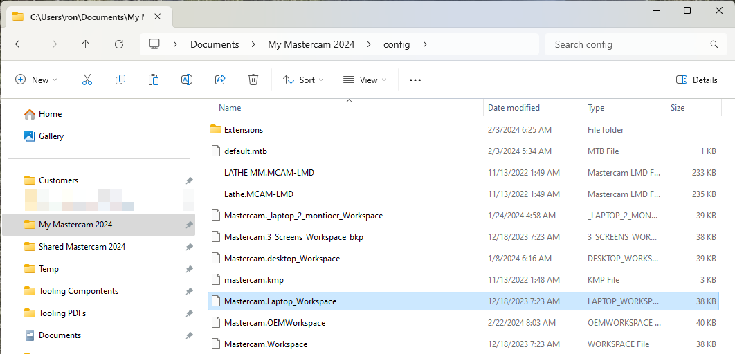
I have been doing a ton of traveling this year and have had many different screen setup to deal with. My home setup is (3) 27" Asus Monitors using a dell docking station. One the road I may have to mirror my laptop screen with a TV or monitor to teach Mastercam. Other places I have 2 monitors I can use. This can be changed each time and things moved around or I can just different workspace files. This is my current process by having backup copies of the different screen layouts and then just delete the current workspace file and then copy the one I need and rename back to mastercam.workspace I could write a BAT file to do this, but in less than a minutes I can make the change and so just do in all manually. HTH
 3 points
 -
Also https://www.mcmaster.com2 points
-
It is supposed to, as long as you use the offset pattern type. It looks like it's not being enabled correctly? It does in 2022, at least (I had that opened already, so I checked there :)).1 point
-
Undercuts only work when set to Offset instead of Dynamic Type, however, it looks like in 2024 it doesn't enable it at all. Looks like a bug to me? I'd report it to [email protected] with your file.1 point
-
Most manufacturers have models for downloads. on their website.1 point
-
You are right, this distance can be controlled by parameters and can be adjusted according to needs. good!1 point
-
https://schunk.com/us/en/workpiece-clamping-technology/manual-clamping-systems/c/PUB_8334 www.raptorworkholding.com https://www.mate.com/pages/metalheads/ To name a few...1 point
-
Decrease the gap size and get full rapids.1 point
-
No, but ProDrill was originally a 3rd party addon produced by MoldPlus I guess Mastercam bought Prodrill from MoldPlus at some point??? Let's take a trip in the way back machine. MoldPlus Prodrill for X2-MR21 point
-
https://www.kurtworkholding.com/resources/cad-drawings/1 point
-
I realized at some point that I was doing a version of this way back when I was turning handles. just whip that thing as fast as you can!! Then there is the age old debate over extra wear on the machine vs. wearing the tool. Still, HSM and RCTF is the way to go!1 point
-
great read! this was the one that really set it in stone for me: ( I'd start at 2:45:00 LOL )1 point
-
When I bought the lathes with Shopturn (this was 810D), I had looked at Fanuc Manual guide and laughed. And also wasn't "that" impressed by Mazatrol (on an Integrex i200). The Siemens was awesome, and latterly fully endorsed by the late Tim M. I never looked at the Okuma though - didn't know anyone in the UK with one but was also far too spendy for my short arms1 point
-
DING DING DING When running high feed cutters, in my experience, when climb should have worked best, conventional cutting has worked better, as well as the opposite case. It is highly dependent on toolpath style as well as material and part shape. When running in Ti, Inco, or other super alloys, I now always advise my customers to try both ways. I have seen 3-5x differences in tool life with zero difference in processing time or speeds and feeds. When you get that much more life often I have been able to really boost productivity by then balancing the tool life with speed and hitting the right tool change interval. Let's just say you get 1 part going climb, you switch to conventional and you get 5 parts. You then increase the speed 30%, and now you get 2.5 parts. So you bump it up 5% more and now you get 2.1 parts and change them at 2 so you have a little wiggle room. 35% on productivity is huge and think, you are using 50% of the inserts you were. It's a made up example, but to Ron's point. TEST TEST TEST, you won't know unless you try.1 point
-
Such a deep subject to think about that I think others have touched on the different things to consider. Testing and seeing where the best ROI gives is what really needs to be done.1 point
-
Well it might be and right now I have a file pulling 109gb with just Mastercam crunching a stock model across 16 cores.1 point
-
Yesh you must just be doing simple blocks with holes in them. They want more than that and you should be okay. They want you to get some serious programming done then they need to get you a serious computer to accomplish that task with. I run a i9-9980HK 16 core Overclocked to 5.2 ghz with 128 gb of RAM with Samsung 970 Pro 1TB M.2 SSD and Quardo RTX-5000 16gb of memory. Next System will have Latest i9 over clocked with at least 16 cores, 256gb of memory and maybe the RTX-8000 32 GB card in it. I will be looking at Dual Samsung 980 Pro 2TB M.2 SSD in Raid 0 mirror for performance setting using a dedicated Raid card. I priced a system like this for $32k so I am dreaming thinking I will ever be able to afford it, but we don't think we can we will never will.1 point
-
This is also an excellent practice. I do find it to work better on "smaller scaled parts". However, it also depends heavily on the "Tolerance" in addition to the Scale of the part. For example; lately I've been working on a bunch of "Micro-Mold" type parts. The tolerances I'm using is around 0.0001-0.00001 mm. At those scales, many of the functions in Mastercam are "input limited", to where I can't enter 6 decimal places in Metric. (Which is what I really need, for the scale I'm working at on a Yasda YMC650.) To make this clearer; I model my parts at 0.000001 mm Tolerances, because the accuracy I need is so tight. I find that you always want to be sure your "input geometry" is as accurate as possible. I like to go for 2 orders of magnitude "more accurate" for my geometry, than the resolution of the machine's least input amount. What is that so? Why do I want my models 100 times more accurate than my NC least step increment? Because the Toolpath Algorithm has an easier time calculating the "tool offsets", if your input geometry is highly accurate in the first place. I want to be sure all the lines are perfect, that all the arc sweeps are accurate, and endpoints like on a "machine grid point". One huge thing to be aware of: when you enter a 'Tolerance' in the Stock Model dialog box, the Stock Model Algorithm will actually "offset" the model that is calculated, by this amount. What I really want with a "meshing tolerance", is "accurate stock edges", but also the ability to specify the "size of the mesh" by giving it a tolerance. I find that for "the most accuracy", you are better off running large roughing Ops through Verify, and saving the STL Model out, with several different Mesh Tolerances. Then, I check the Saved Folder, to see the actual physical size "on disk", to get an idea of "how big is the model". I will then perform a "File > Merge", and change the File Handler to ".STL Files" (Stereolithography). I check the 'Options' to make sure it is set to 'Mesh' only, and not 'Stitch'. Select your STL model, and when the Function Panel appears on the left side of the screen, set the Radio Button option to "Active Level". Finish the Import with the Green Check Mark. Now, click on the P-Mesh entity (you just Merged), and click F4. (Analyze Entity Properties.) Note the # of triangles. You can then perform that same set of steps, to Merge in several different P-Mesh Models, that have been 'exported' from Verify, with different Tolerance Values. Note: When you export the STL from Verify (as long as the "Precision Slider" is advanced all the way to Precision), the Mesh will be calculated "on the actual 'cut edges' of the Stock that is rendered in Verify. The 'Export Tolerance' in this case dictates the actual size of the triangles which are generated. What you are looking for is 'acceptable quality' (render without edges visible, and check the surface smoothness), while also being the most compact "size on disk" possible. When you use a 'Stock Model' in the Ops tree, especially one that is tied to an Operation, or multiple Operations, that Stock Model will require a regeneration, every time you make any changes to the parent operations. For me, the cutoff is typically 5 minutes of generation time. If the Stock Model takes longer than a minute to generate, then I really start to question "do I need a Stock Model here, which is tied to a set of Operations?" Because I know that every time I have to generate the path, I'm going to incur that computational overhead. So, if I'm doing "less complex work", where I can run 30 Ops through a 'Stock Model', and it generates in 10-30 seconds, then I keep using Stock Models, and everything works great. Once those generation times get above 2-3 minutes, that is when I start considering "Export STL > Merge P-Mesh on Level > Tie Stock Model to 'P-Mesh' scenario. I find it takes about 2-3 minutes to do that process, so in many cases, it can save considerable time to not create a "Stock Model Op > Tied to a Toolpath Operation". This is my life lately:
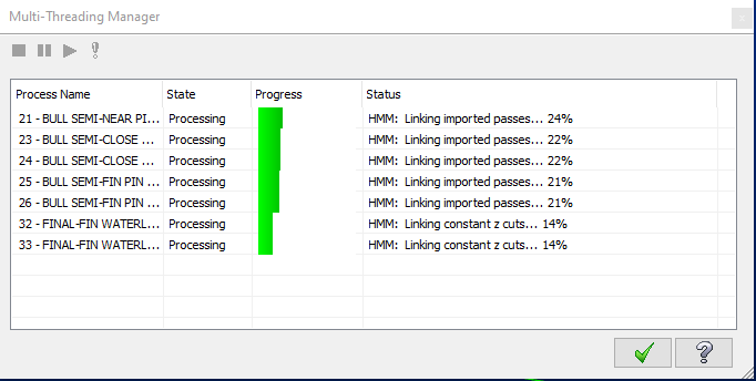 1 point
 -
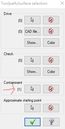
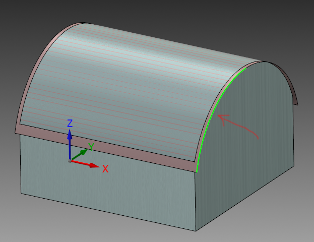
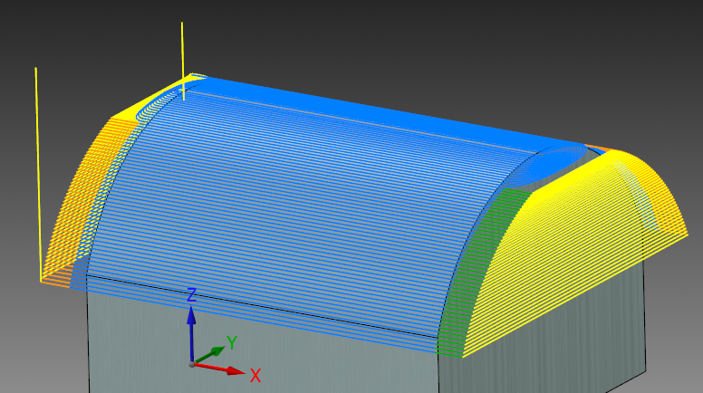
Also, I don't mean to criticize at all, as I've missed plenty of mistakes myself. But you should be using the Verify > Compare function, to be sure your cutter is only removing material where you expect to remove it. Whatever 'geometry' you have visible on the screen, will automatically be transported into verify, as a 'Workpiece'. This is the part that will be 'compared' against your stock. In the 'Simulator Options' dialog box, you get to select your 'Stock' for Verify and your 'Fixture' for Verify. I typically setup a Stock Model to act as my 'initial stock', and also can use a Stock Solid. (Note: you have to select it on the screen when using the Solid option.) When you load Verify, there are Checkboxes for 'Stock', 'Workpiece', and 'Fixture'. If you want to detect 'collisions' with the Fixture and/or Stock, you have to enable the 'collisions' option, under the 'Stop Op' options (pop-out menu). Also, set the Collision Checking options in the configuration menu for Verify. After you have 'played through' all of your cutting Operations, you can go to the 'Verify' tab, and use the 'Compare' Function. The Compare Function Panel will display (usually on the right side of the screen). Here you can enter a 'Stock amount', which is your "Stock to Leave". This will make an 'offset' from your Workpiece, which is now the 'zero target stock amount'. This can easily help you catch mistakes that you miss in Backplot.1 point
-
Happy Easter Friends ! In the last 5 years I have had my reseller on my screen for tech support 3 times...they were completely lost , from the default screen etc.0 points
-
Thought your company was not on active maintenance, but you can open a 2024 file?0 points


.thumb.gif.b2f8d84f284177ecd2bf348424895690.gif)