Leaderboard


Popular Content
Showing content with the highest reputation on 04/25/2024 in all areas
-
A bit of a shortcut in your method is that you can skip the "extend the two lines to their intersection point" when you create the circle. Just hit "i" key or AutoCursor > Intersection and choose the two lines, it'll snap to the intersection. ----------- You need 2 pieces of information to create a tangent arc. If you have those two pieces of information, you can calculate the missing 3rd, right? There's a critical piece of missing information to solving this, which is either the tangent point (on the bottom line) or the radius. Without specifying those two, there's an effectively infinite amount of possible answers. When you extend the bisecting angle lines, you're creating the restriction on the radius (1.50881301") so there's only one solution that fits the end point of the slanted line and the center point (Radius), which means you'll get a tangent point on the lower line at X0.57622467". Unfortunately, unless you have a specific reason for choosing the centerpoint you did (i.e., it's called out by the print to find the bisecting angle between these two features and create the radius centered off of that?) it's just really a random point in space that confirmation bias makes look more likely to be correct Note that Tom found the solution in solid works effectively the same way, using Constraints instead of the geometry.. If you use Mastercam's Arc Tangent > Arc One Point, you're now constraining two items: The end of the angled line and whatever tangent position is closest to that line. Mastercam will make an arc fitting with whatever radius you type into the panel. You can make a Arc Tangent > Arc Two Entities, which will do exactly what fillet would do, (in the background) it'll extend the angled line to the intersection and fit an arc of 1" (or whatever you specify). ----------- Basically, you're not asking the right question. For two lines of N angle, you can ask: What radius fits between these lines? Any of them, pretty much. What radius is a fillet? How many windows are in a house? If I give you a point and a line, what radius fits between those two? Any of 'em > the distance between the closest point to line. See above. If I give you a radius, where does that fit from this point to a tangent point on this line? THERE YOU GO! That's the right one ----------- I can't imagine that any CAD/CAM system can give you what you're asking for, as you're not giving complete information.5 points
-
Sorry, misinterpretation on my end. You weren't finding an issue with the original question, you were providing a more in depth explanation to the provided solution. Thank you sir, this is much appreciated.2 points
-
Sorry if I used too many words Correct that Mastercam doesn't (to my knowledge) have a way to create an arc from two tangent lines and a single contact point. Yep, I was going off of the original problem (at the top of this reply). What I'm saying is your second reply where you added the video gave the crucial constraint, at that point you've completed the puzzle. I'm guessing you'll be able to chook it fairly easily now that you've figured out how to do it. It probably hasn't come up enough for someone at CNC to take a look at it, because how often is this scenario encountered?2 points
-
Went to add an edit and couldn't, but this should've gone with above post. So, OP, when you get blank pages like that it's typically because you aren't following the correct structure. It's difficult for me to make sense of the structure you have in place right now. My main sheet is (FILE), which calls (MILL-FILE), which calls (MILL-TOOLS), which calls (MILL-TOOL). Assuming you have (FILE) shown, you're then calling (FILE) and (MILL FILE) in the same report. Then one each of those calling (OPERATION) and (MILL TOOLS). I don't think that structure is agreeable. I think you need to be (FILE) - (MILL-FILE) and have that calling both (OPERATION) and (MILL TOOLS).2 points
-
Here you go This is a zipped Mastecam file the radius in 3.0176/2 solved Create_Arc_Sample.zip2 points
-
Thanks for the reply! Wanna make sure I understand this statement correctly. You're saying the original question does not have enough information to solve. This is because to create an arc tangent to a line, you must specify the tangent point. The tangent point cannot be derived for the bottom line without the radius, and the radius cannot be derived from the given info (a line and a point on the line). But don't I disprove this in the video I posted? Like you said, I derived the radius from the given information. Mastercam should be able to do the same thing I did in the background.... right? I disagree with this statement. The reason I chose the centerpoint I did was because of the original question. I want an arc tangent to the endpoint of the angled line. Only one arc exists that has this characteristic and is also tangent to the bottom line. It's entirely possible I'm misunderstanding something here, so please correct me if I am. With that said, I think we all agree Mastercam is not capable of solving the original question "easily". After thinking about Aarons response and writing this reply, I realize I have the capability to attempt to write a chook to solve this issue. I should have time tomorrow night to dig into this. Maybe I'll be another victim of Aaron's signature (love that signature BTW), maybe I'll make something that works. Either way I'll be back with an update. Another huge thanks for all the replies. Seems like it's been mostly machine-control or mill-turn related questions on eMC recently, was nice to get a CAD discussion going.1 point
-
We can't use "Fillet" because we don't know the radius.1 point
-
Doing it in NX I also get Ø3.01761 point
-
We did this in CATIA and got Ø3.0177 In SW I got Ø3.0176 In Mastercam I got 3 different results, none of which agreed with CATIA/SW I'm going to refer this Mastercam QC1 point
-
This is ridiculous. Solidworks gave me Ø3.0176 Doing it Bird's way in MC2024 I've done it 3 times and got 3 different answers In SolidWork Start a sketch, sketch a circle in space constrain it to the horizontal line with a tangent constraint constrain it to the point with a coincident constraint constrain it to the angled line with a tangent constraint I'm going to ask our Catia designer to solve this in Catia and see what he gets.1 point
-
Restore initial settings...1 point
-
I got 3 point to work, toggling "Tangent" on and off as I selected the three entities, but I was not confident the result was good. Certainly not confident enough to use the resulting arc in an program1 point
-
If you do not use a second point or specify radius, there will be no solution. I just tried two entities and you can adjust the radius size until you get really close to the vertical line. It would only be an approximation but short of getting out the old trig book it will work. Start small and work it up.1 point
-
I sketched something similar to your screen shot and tried this. I couldn't come up with a satisfactory solution. This problem is 15 seconds work in a parametric modeling software like SolidWorks.1 point
-
What if you extend the upper, angled line beyond the intersection point, so it's tangent, rather than an endpoint? I'm not on MC at the moment to try it, but it seems like it might like that better.1 point
-
Here's a video showing another workaround to get the arc I want. Dropbox - Create Arc Workaround Example1 point
-
Try using "arc tangent/arc one point" select the line, then the point that you wish it to go thru. You can then set the radius/diameter of the arc you need. Sorry just noticed this doesn't create tangent arc on the angled line1 point
-
Create Arc - Tangent >> to 2 entities1 point
-
Well, a big thing I notice is you haven't shared a z2g file...really the only way someone can dig in and see what's up1 point
-
Our shop has a handful of 90s FANUC controls, lack of memory is my top concern when programming for those machines. I have a few thoughts that may help you out: -You should look into an operation repeat macro to make multiple parts. It will save you from needing to use Xform + subs to make a bunch of parts. Our posts are set so that we can specify how many times we need to run a tool at the machine, based on setup needs, with a default of 1 part. At the end of the tool's work, it checks to see if there are any more offsets to run, then increments and re-runs, or moves to the next tool. Our machines use G54-9, J01-29, so we increment the J value to repeat multiple parts. YMMV based on your control and how many offsets you have available. This method lets you program for one, and make 3 at once. Then next time make 10 at once if you need to. -Take a look at your filtering settings, and hi-speed ruff with 0.005-0.010 as the tolerance (~1/2 stock to leave usually). Be sure to check the box that says "Output 3D arc entry motion" too. That will clean up your helical entries. Know that while dynamic HSM is fun, and fast to program, if your machines can't handle it, they can't. Often a facing, pocket, contour or 2D blend toolpath with a 10% stepover can get you into HSM feed numbers and keep your tools running on lines and arcs. These methods will take a bit more time and effort to set up, but well worth it for memory starved machines. I have run hi-speed, or hi-speed-lite™ on our machines with 60-128K of memory. Also there is a lot of discussion on "why not drop 2TB SSDs into machine tools", and it boils down to the type of flash they used on these boards. They are designed to last for decades in a shop environment, and still work around the clock. There are threads here, and on PracticalMachinist if you want to look up the specifics. I'm not absolving the MTBs of the insane pricing for memory, but supply is scarce for old parts now too.1 point
-
Hahaha that's exactly what I have done. It's painfully annoying trying to even get my modifications to go as I'd like. I've thought about trying to convince the boss man to get Varco Reports. I have heard great things about it. http://varcoreporting.com/ I can see they already have feed/tooth shown
 1 point
 -
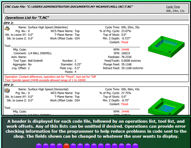
Since many people have asked me to share how this works, I thought I would make a post about setting the Control Definition Default settings. Are you tired of your NC code changing whenever you update Mastercam? Why do your NC settings seem to get screwed up? You ran the "Migration Wizard", and things are still broken... Ok, so what's going on? ---> You didn't set the Control Definition Default Settings. It doesn't have to be this way. You can setup Mastercam to handle upgrading without causing you frustration, or the loss of any hair/sleep. Here is a step-by-step process for setting the Control Definition Defaults. What is a Control Definition, and why should you care?: First, what is a Control Definition File? A Control Definition is a file that Mastercam uses to store settings for controlling your NC code output. The CD (Control Definition) contains common settings for things like "Arc Formatting", and the settings for Sequence Numbers (N numbers), among other things. The idea behind the CD is that it gives the programmer the ability to adjust settings by using a Graphic User Interface, instead of having to make edits directly to your post processor. When it was originally conceived, the CD was created with the ability to link and control multiple post processors, and have separate settings for each one. This would give "administrators" the ability to make edits for multiple machines from within a single file. In practice however, nobody ever does this. Every shop that I've worked with uses a single MD, CD, and PST file, all with the same name. So even though a machine might share all the same settings with another machine in your shop, the "best practice" is to use a single MD/CD/PST name for each unique machine on your shop floor. When you create a new job in Mastercam, and load a "Machine Definition" file into your Ops Manager, Mastercam places a copy of your MD and CD into the Ops Manager. These "file copies" are specific to your individual Mastercam file, and are not "linked" back to the originals (or "library copies") of the files. To a certain extent, this does make sense. This convention allows you to make "individual" file changes. So for example, say you had a program that used a Right Angle Head, with a few specific tools. You could setup the "stations" with a RAH component, and have all of those options saved inside your individual Mastercam file. You wouldn't want all those modifications to be made to the "library copy" of your files; they are project specific. Another situation might come up where you are running out of memory for a specific program. For this individual file, it might make sense to disable Sequence Numbers, remove all the "Space characters", and output all of your Arcs using "R" values instead of IJK, just to save space. The CD allows you to do that, without changing the settings in the Library Copy of your CD... Are you with me so far...??? So in a nutshell, the CD contains user-select-able parameters that control some of the formatting of NC code output. Control Definition Defaults OK, so the CD contains settings that format output from the post. Great. Now we get to the issues... The main problem that I see people run into comes when they update to the next release of Mastercam. This problem occurs because the settings in the CD refer to a static file path. Say what? Yes. The settings that are stored inside the CD are stored for a specific post in a specific file location. Those settings are only valid for that exact post processor file name, in the exact folder location you specify. When you setup a new post processor, most users typically create (rename, whatever) a new post, and put it in a specific folder, local or network folder location. Ok, great. But then they go and "link" their CD to that Post Processor, and take the time to configure their CD. This is all well and good, except, that they don't know about the static file path issue. Every Control Definition file has a set of "Default Settings" that are used (you might have guessed), by default. That means that whenever you move your post file to a new folder location (this happens "by default", every time you upgrade Mastercam), the settings for the CD that link your "new" (updated) post processor will revert back to these "default" settings... "Aghhhh!!!!" . . . "WHY!!!!" I can hear the screams from all the frustrated users dealing with these upgrade issues... So, what can be done to solve the problem??? Setting the "Default settings for control type" Ok, start by opening one of your CD files in the Control Definition Manager. Click on the "drop down" arrow for selecting a Post in the post file list. At a minimum, you should have the file path and name of your currently "linked" post processor, and there will be at least one other entry in the list; "Default settings for control type". <--- These are the "default settings" that will get picked up, whenever Mastercam is updated to a new "major" version. So, lets say that you have spent a bunch of time tweaking all of the parameters for "your post". To import those settings to the "defaults", do the following: Open your CD file in the Control Definition Manager. Select the "Default settings for control type" in the "Post Processors" drop-down list. Select the "Tool" page in the Tree. (any page will work, I just picked one for the example.) Move your cursor below the controls, into the "gray area" of the page. Right-Click in the gray area, and you'll get a Right Mouse Button Menu that pops up. Choose "Import > All pages". This launches a "Open" dialog box. Mastercam is asking "which CD" do you want to import the settings from. By default, it will have the currently open CD set to the current file name in the dialog box. Just press "open", no need to re-select the file in the list... This opens a "Control Import - select the type and post key" dialog box. There will be a list with "your" post, the "default settings for control type", and possibly some other file paths, depending on how the post was originally setup, and if it has been "updated" previously. Choose "your post" in the list. Press the "ok" button. All of the settings from "your post" have now been imported into the "default settings for control type" in your CD. Press the "save" button. Doing that process will import all of your current post settings to the "default" settings for your CD. Now, whenever you update Mastercam, the CD will use the "default settings", which just happen to match your current post settings. You will never again have an issue with a Mastercam update changing the NC code output of your post... A few caveats: If you start by just simply taking a new CD file, and setting the "Default settings for control type", you never have to worry about "importing" any settings, since any post that you then link will pick up the "defaults" automatically. If you change any of the parameters for your current "library copy" of the CD, you should also make those changes to the "default settings", or you risk getting your current CD settings, and the "defaults", out of sync. If you do make any changes to your current linked post, just remember that you can "import" those changes to the default settings with the procedure above. Make sure you set the Default Settings for you CD in your current version of Mastercam, before you run the Migration wizard. I thought you could import CD settings from older versions of Mastercam .control files, but it doesn't seem to be working in X9. Hope that helps, Colin1 point
-
Haas Z axis are notoriously unstable. I am running an UMC 750 and the spindle often grows 0.002 through the day.1 point
-
Yes. Go into each CD, with your 'linked Post Processor' selected in the drop down menu. (Should show a green check mark). Check all of the pages, make sure all the setting are 100% how you like them. Save those settings. Then, select the drop down menu, and choose "default settings" in the drop down. Go to the 'Tools' page, right-click, import > all pages. In the dialog that pops up, choose your existing CD file. That will bring up the dialog to import the data. Choose your existing Post from the list. This will tell Mastercam to import all the settings from your "linked post" into the Default Settings. Now, save the Control Definition Defaults. When you run the Migration to 2018, every single Control Definition setting will match what you setup in 2017, and will match 100% of the time, every time you update to a new version.1 point
-
One additional thought I have when you are having trouble is to start fresh. Here is a procedure for setting up a new MD, CD, and PST file, from scratch. (Well, at least starting from the unmolested "default" files anyway...) To create a new 5 Axis Mill Machine, Control and Post, do the following: Start by taking the "Generic Fanuc 5 Axis Mill Post", in the "mill\post" folder, and make a copy of the Post. Also make a copy of the PSB file. This is the "binned" or encrypted portion of the post. You must have both files, together in the same folder, and they must have the exact same name. In this case lets name each file "5X_TRUNNION_MILL". So you will then have "5X_TRUNNION_MILL.PST" and "5X_TRUNNION_MILL.PSB" in your folder. (Hint, while renaming the first file, highlight the file name only and press CTRL + C to copy the file name string.) Go to the "CNC Machines" folder, and copy/paste the Generic Fanuc 5X Mill.Control-8 file, and rename the copy to "5X_TRUNNION_MILL". (this is where having the name string copied to the clipboard helps.) Do the same thing for renaming the "Mill - 5 Axis - Table / Head Vertical" Machine definition. This is the only file of the four I listed that has a different "default name" from the "Generic Fanuc 5X Mill". Name the MD to match the other files. Now that you have all files named the same, except for the file extensions, start with a "fresh" session of Mastercam. (close and re-open if necessary, or do Machine Type > Design, then File > New.) Open the Control Definition Manager. A small dialog will appear that allows you to open an existing CD, or create a new one. Browse to, and open the new CD you created. Click on the Post Processor button. There will be two entries in the list; the "default settings", and a linked PST file. Select the linked post, and use the "Delete" button. That leaves only the "defaults" in the list. Close the select post dialog box. Save the CD file. Edit the "Default settings", until every parameter is setup the way you want it to always be. Save the CD file again. This file now has the proper "Default" settings for your new machine. (There will only be a "anti" sign (circle with slash) next to the Defaults, because they are not linked to a specific post processor.) Now, press the "Post Processors" button, and use the "Add" button to add a new post. Browse to the post you just created/renamed. This will add the entry in the list. Press "Ok" to close the selection dialog. In the Drop-Down, make sure the new post you just added is selected. You will see a "+" plus sign next to the post. The Control Definition Manager may warn you that "you are selecting a new Control Definition, do you want to save the existing definition", or something like that. If it does warn you, just say "yes" or "ok". Press the Save button. Mastercam will validate your post, and put a Green Check Mark next to the linked post. If you don't have a green check mark, your CD settings are not linked to the post processor. Close the Control Definition Manager. Open the Machine Definition Manager. Edit the Kinematic Components to represent your actual machine configuration. NOTE: the MD does not control any of the NC setup or output. This is done for the 5 Axis Post, inside the post only. The 4X post reads some data from the Rotary component for the 4th Axis. But only with a 4X Post. The 5X Post is only setup inside the post itself. "Then why setup the Kinematic Tree at all?" <-- I can hear you ask it now. Because the Tool Paths themselves are checked for compatibility with the MD kinematics. Set your Coolant Options in the MD. Make sure the MD is linked to your new CD. Save the MD. (NOTE: for 5X machines, you will need to fully configure the PST file settings!!!) That's it. Your MD, CD, and PST files (PSB too, for 5X), all have the same name, and are properly linked together. The process is the exact same for Lathe, or Router, just substitute a LMD or RMD file, instead of the MMD. The process is also the same for a 3X or 4X post, without needing to worry about a PSB file. The 4X Post does read the Rotary Component settings for things like "continuous rotary" or "index only", the rotary direction (CW vs. CCW). It does not read the Rotary Axis Limits.1 point
.thumb.jpg.e1ed32e8dc33a68b1f20806bb5d55e08.jpg)