SuperHoneyBadger
-
Posts
146 -
Joined
-
Last visited
-
Days Won
4
Content Type
Profiles
Forums
Downloads
Store
eMastercam Wiki
Blogs
Gallery
Events
Everything posted by SuperHoneyBadger
-
I know we figured that these synergistic moves were going to be part of the Sandvik deal. Didn't know we would have to pony up for a subscription, lol. Also, the BUY NOW button next to the tools is missing. https://www.sandvik.coromant.com/en-gb/tools/digitalmachining/coroplus-tool-library/coroplus_tool_library_add_in_for_mastercam Aside from suggesting tools and inserts, EXTREMELY relevant to know how many grams of carbon emissions each tool will be responsible for. I know I have always been worried about that - for roughing passes especially.
-
Construction Levels? Everyone always wants another CAD feature around here, eh?
-
Custom Setup Sheets vs. Mastercam ones
SuperHoneyBadger replied to sharles's topic in Industrial Forum
I'll get around to throwing in a G54.1 P18 once that sheet gets released to the boys, lol. -
Custom Setup Sheets vs. Mastercam ones
SuperHoneyBadger replied to sharles's topic in Industrial Forum
Yep. That's absolutely the reasoning behind our simple sheets. Get the Ø right, get the length right, get the tool number right. That's all I ask of you, Mr. Operator. -
I'm sure once you have gone through the training materials suggested above by an esteemed community member of high regard, you will be quite adept! Even if you use them only to search for what you need doing at a certain point in time. Though I do suggest starting on 2D mill and working through the whole thing, as you are new to the software. I know you will find the guidance you seek, and to be Frank, everyone here will be willing to help you out once you dive into the training manuals!
-
Custom Setup Sheets vs. Mastercam ones
SuperHoneyBadger replied to sharles's topic in Industrial Forum
In all honesty, I have been in full avoidance mode when it comes to AR. I'm hoping that my IKE tinkering will bear fruit, and I'll be sure to let everyone know if it does. Especially if it is a more global kind of problem to solve. -
Custom Setup Sheets vs. Mastercam ones
SuperHoneyBadger replied to sharles's topic in Industrial Forum
This is what I have so far from IKE. Having a hard time with the tool depth on these sheets as the Z Depth variables (pcomm_max_min_file, pcomm_max_min_tool and pcomm_max_min_op) seem to only output the depth for the lastOP the tool is used for, not the deepest point versus Z0. Working on it on the side of regular duties. I will say, the post itself pumps out good code (but still needs mods for our subs/macros etc), and has no issues with rotations on our horizonal and our rotary table'd 3 axis. I use it for axis substitution on the rotary when I need it.
-
Yea. If the big guns' request falls on deaf ears, you're right, we'll get Dynamic Delete first...
-
Custom Setup Sheets vs. Mastercam ones
SuperHoneyBadger replied to sharles's topic in Industrial Forum
My guy. We are dealing with vastly less complex components over here in the bush leagues. That's an impressive workload to manage and make sheets for. Lots of folks here seem to favour X+ for their setups, and everyone and their Mother's best friend hates Active Reports. I hope you get some thought provoking answers from the vets! -
Levels should have folders/groups, and planes should have more flexibility to organization. Sucks adding a few in, or working on a big file that has no semblance of order in the planes manager. I often just sort by offset number to get all the used ones near the bottom. It's less than a band-aid solution, IMO
-
Custom Setup Sheets vs. Mastercam ones
SuperHoneyBadger replied to sharles's topic in Industrial Forum
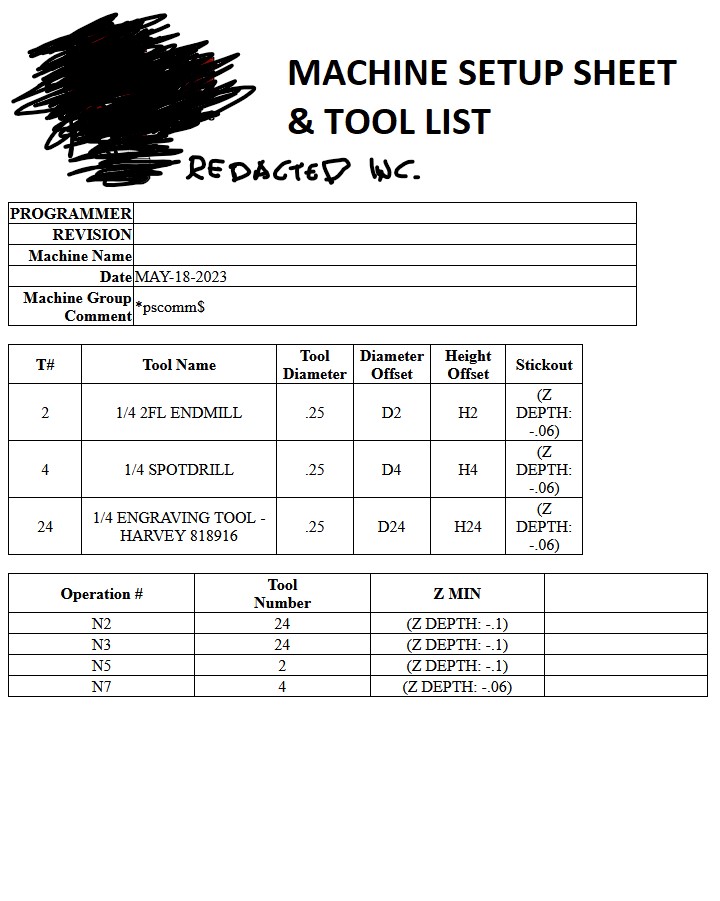
We are a job shop with an unforeseeable mix of low and high volume, sometimes one offs. The philosophy is a simple, top/side drawing showing XYZ zeros and clamps etc, and the plain text setup sheet below. The "Setup Instructions" portion is a file that I copy and mod for each job, and is in the mastercam file as a manual entry pointing to a text file. We have a wild post from before my time, and it works for 80% of what we post. Misc variables handle what machine it will post for, high speed or not, etc. I have seen a lot of complex setup sheets posed around here, we have a system that gives you a tool type, tool diameter and total Z engagement below Z0. It all gets posted after the M30 as you see it below. The operator takes that info and builds his tools, I make some notes in the tool name if we need extra clearance or grindback: 1/4 CARB EM 4FL - CLR 2.0. Usually just knowing how deep a tool will go is enough to pick an endmill. The most I have handed someone is three sheets of paper for 1 OP. Usually it's two, and one is a nice drawing I made. I have also been tinkering with the IKE post and it's auto setup sheet, but I can't get all the functionality of the sheet below. Yet... I will. RECORD CYCLE TIME HRS: _______ MINS: _______ NO. OF PARTS: ____ MATERIAL: 3/16 - NITRO-V STEEL PLATE BLANK SIZE: WATERJET BLANK MILL TO: OP1 COMPLETE PARTS PER BLANK: 1 ***************************************************************** SETUP INSTRUCTIONS: ***************************************************************** HORZ ONLY HOLD ON FIXTURE 4731-0 ØTOOLING BALL IN .250 HOLE FOR MEASUREMENT BOLT TO FIXURE USING CLAMP (4731-5): 2X 4-40, 2X 1/4-20 G54 - B0 X=0 AT C/L OF TOOLING BALL Y=0 AT C/L OF TOOLING BALL Z=0 AT TOP OF TOOLING BALL G55 - B63 X=0 AT C/L OF TOOLING BALL (AS PRESENTED) Y=0 AT C/L OF TOOLING BALL Z=0 AT TOP OF TOOLING BALL (AS PRESENTED) G57 - B297 X=0 AT C/L OF TOOLING BALL (AS PRESENTED) Y=0 AT C/L OF TOOLING BALL Z=0 AT TOP OF TOOLING BALL (AS PRESENTED) SEE SETUP SHEET ***************************************************************** MAX SPINDLE SPEED = S15000 OVERALL MAX - Z2. / OVERALL MIN - Z-.8621 N10 G54 B0. T5 H/D#107/8 // TD( 0.5000 ) MIN_Z= ( Z-.4509 ) 1/2 CARB EM 4FL - FIN N20 G54 B0. T12 H/D#107/8 // TD( 0.2500 ) MIN_Z= ( Z-.4509 ) 1/4 CARB EM 4FL - FIN N30 G55 B63. T7 H/D#107/8 // TD( 0.7500 ) MIN_Z= ( Z-.8621 ) 3/4 BULLNOSE 4FL - RUFF N40 G57 B297. T7 H/D#107/8 // TD( 0.7500 ) MIN_Z= ( Z-.8611 ) 3/4 BULLNOSE 4FL - RUFF N50 G55 B63. T17 H/D#107/8 // TD( 0.7500 ) MIN_Z= ( Z-.857 ) 3/4 CARB EM 4FL - FIN N60 G57 B297. T17 H/D#107/8 // TD( 0.7500 ) MIN_Z= ( Z-.856 ) 3/4 CARB EM 4FL - FIN N70 G54 B0. T12 H/D#107/8 // TD( 0.2500 ) MIN_Z= ( Z-.4509 ) 1/4 CARB EM 4FL - FIN ++++++++++++++++++++++++++++++++++++++++++++++++++++++++++++++ !!!! TOOL FEED INFO !!!! t5 5 FEED- 6 PLUNGE- 50 RETR = 400 RPM - 1500 // EXT LGT = 4. FL/LGT = 1. t7 7 FEED- 4 PLUNGE- 50 RETR = 400 RPM - 1000 // EXT LGT = 2. FL/LGT = 1.2 t12 12 FEED- 10 PLUNGE - 50 RETR = 400 RPM - 3000 // EXT LGT = 4. FL/LGT = 1. t17 17 FEED- 10 PLUNGE - 50 RETR = 400 RPM - 1000 // EXT LGT = 4. FL/LGT = 2. -
Another method for renaming on-screen solids is to select one and hit F4 (or your shortcut for Analyze), top of that window is a field for the name.
-
Extremely useful way of using it. Did an up-rev'd part not long ago and used the section view + edit to inspect where the holes got close to the part walls. Gave me a good idea of how far to poke the drill without breaking through. I also made 2 separate planes I could section with to check backplotting, if you use this feature more I'd map it to a keystroke. I have mine on Shift+S to toggle it and check my work while I go.
-
Where is “Enhancing Model” feature in Verify? - Mastercam 2023
SuperHoneyBadger replied to M Ham's topic in Industrial Forum
Noticed in 2024's Sim I need Verify>Quality>Accurate Zoom a fair bit more than I did with 2022 to see that crispiness. Also, leave Turbo Mode off in the same area, and try jiggling with the Performance - Precision slider right of the transport buttons at bottom middle. Might help some with your initial views. Also, don't forget Reset Zoom once you have used Accurate Zoom, as it cuts off what is outside of your current view -
Mastercam 2024 available for download.
SuperHoneyBadger replied to #Rekd™'s topic in Industrial Forum
My most improved feature is viewport performance, moving from 2022. Even a simple solid would chug-a-lug when rotating, only started noticing after moving from a 1080p monitor. But now on 2024, she spins like a top, and holds near to 60FPS even with materials on, with a Quadro K620 @ 2560X1440. Also, after my remedial classes on the new stock setup, I'm quite happy with Twenny Four. -
2024 - Stock Setup (Yes, Another Thread)
SuperHoneyBadger replied to SuperHoneyBadger's topic in Industrial Forum
Was out sick end of last week, thanks so much for your prompt reply, it was EXACTLY what I needed. Also, the stock model in-situ functionality you mentioned will be leveraged heavily. Right before I verified OP2: I went to Stock Setup and set my OP1 Stock Model to the active stock, because I was unaware of the new functionalities. -
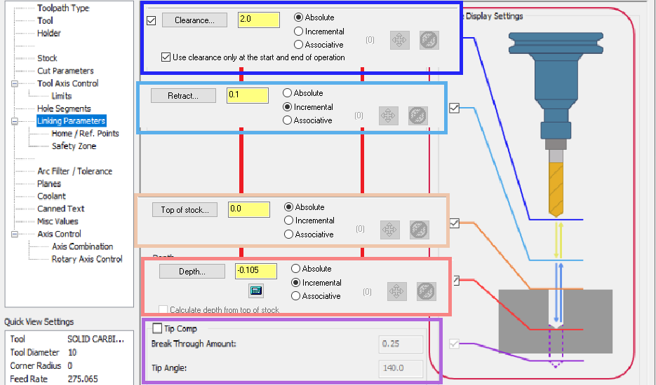
I tried to like it, guys. I really did. Genesis: Skipped 2023, jumped in to 2024 from 2022 on Monday. Normalement, I set up a bounding box on layer 15 (useful to make setup sheets and measurements), and use that to define my stock in Stock Setup. Cool. I can still do that, if anything it's a bit easier/more flexible, and I like having a little library of multiple stock models there. After OP1 is programmed, I make an "OP1 FIN" stock model to verify OP2. What I would do next is never go back into the Stock Setup dialog again, but change the Simulator Options tab to my stock model, "OP1 FIN", verify and then make any changes. For checking the whole program, Simulator Options > Stock Setup, boom, verify OP1 and 2. In 2024, we have no option to have this 'secondary' stock active without making all the stock aware toolpaths from OP1 dirty by "activating" a mesh/model that these paths aren't expecting. For a quick G54 + G55 job, not the end of the world. But I don't want to have to lock, change stock, change back, unlock, then regen 40 million toolpaths on a big part. Having the Stock Setup and Simulator Stock separate didn't seem like a luxury at the time. Let me know if I'm barking up a tree or looking in the wrong place for my 'secondary' stock options for MC Verify.
-
Isometric, Orthographic vs Perspective view?
SuperHoneyBadger replied to robertcnc's topic in Industrial Forum
The big difference is between engineering design, and artistic design. I have spent my time in XSI SoftImage, Unreal and various 3D compositing environments. Priority there is solely what an object looks like. That category of program doesn't even have the option of handling scale 95% of the time, and units are arbitrary outside of degrees. Model it, UV flow, texture/materials, animate, render, move on. The image/model IS the final product. Priority in CAD/CAM is fit and function, you can't see that in a perspective viewport. The model here is not the final product, but a means to an end. Parallel lines and similar sized features are two big examples that come to mind. Orthographic was selected not only because it was less taxing on the CPUs of the day (matrix transforms for each movement, etc), but because it shows features the same way as engineering drawings were made on drafting tables, and we needed consistency between the physical and the virtual. Hell, we still do. It's not that the projection is antiquated, but necessary to represent 3D features in 2D in a way that is easily, and quickly understood. Dissertation aside, I had my gripes with it initially, moving from the art world into CAD with SolidEdge, where you are allowed to model in a perspective viewport. It's whackadoodle crazy trying to line things up, or make similar sized features. I didn't spend more than a few days struggling, with an old-salt engineer over my shoulder chuckling to himself. -
It was/is a bit of a pain... This thread should help you out, a few videos referenced to show you the new workflow:
-
2022's "old way" fits in the exact same vertical space as the dropdown method... Also, if we're going to colour code the planes in this page, and in the viewport, let's go HARD BAHD
-
mastercam9 Install Master Cam 9 for windows 10
SuperHoneyBadger replied to Okoshi's topic in Industrial Forum
We have MasterCam X on a CD w/hasp. It's the only version we have for lathe, and it serves its purpose when needed. The simplest solution for us is to run a 32 bit Windows XP virtual machine on our Win10 programming rig. There is a bit of setup involved, but once it's done, opens up like any other program. I can't guarantee personally, but likely V9 will work. Big bonus: this method allows older versions to run at 2560x1440 or even 4k, on modern GPUs + CPUs that were mere fever dreams in the '00s. If all you have is an older cut (for whatever reason), maybe this can help you get by. -
Halloween is next month. Loving the big necro energy lately in preparation
-
Form Tapping - Drill Size Formula
SuperHoneyBadger replied to SuperHoneyBadger's topic in Industrial Forum
Thanks all for the informative posts! That calculator is the best I've ever seen online Still no word back from a few sources on the 0.0068, the search continues. -
Had a machinist come to me and ask if I had a form tapping drill chart, and if there was a formula he could use to determine the drill size. Told him it was at the bottom of the page, and he was stunned to see how easy it was. Now. Question time for the community: where does the constant 0.0068 come from in the formula? I have called Emuge, OSG and 2 university mechanical engineering depts. No one on the other end of the phone has a better answer than, "engineers sometimes come up with something that works, and we don't often ask about where it's derived from if everything is going well". Most useful was "...it's related to truncation values, P values, and the include angle of the thread..." % of Thread Desired = Whole number - 65, 70 or 75 Imperial Form Tap Drill Size = Basic Tap O.D. - (0.0068 x % of Thread Desired) / TPI Metric Form Tap Drill Size = Basic Tap O.D. - (% of Thread Desired x Pitch) / 147.06 So the 2 constants are the inverse of one another, one uses pitch the other TPI so that's easy enough, but I'm scratching the old noggin trying to determine where they come from in the first place. Just have to keep calling professors and AE's at tap companies until I get an answer, and I'll post it here if something comes up.
-
I have accepted that when I choose a stock in the Simulator Options dialog it gets reset each time I open MC. Ends up being one of the first things I do in the morning, making sure I'm verifying off the G54 Stock Model, or what have you. Happens with a Stock Model or selected solid, and it reverts back to the Stock Setup radio button each time a file is opened. Not sure if this is a bug or a feature, but my experience is similar to yours. This is observed across 2021 and 2022 as well.