


SuperHoneyBadger
-
Posts
157 -
Joined
-
Last visited
-
Days Won
5
Content Type
Profiles
Forums
Downloads
Store
eMastercam Wiki
Blogs
Gallery
Events
Everything posted by SuperHoneyBadger
-
2024 - Stock Setup (Yes, Another Thread)
SuperHoneyBadger replied to SuperHoneyBadger's topic in Industrial Forum
Was out sick end of last week, thanks so much for your prompt reply, it was EXACTLY what I needed. Also, the stock model in-situ functionality you mentioned will be leveraged heavily. Right before I verified OP2: I went to Stock Setup and set my OP1 Stock Model to the active stock, because I was unaware of the new functionalities. -
I tried to like it, guys. I really did. Genesis: Skipped 2023, jumped in to 2024 from 2022 on Monday. Normalement, I set up a bounding box on layer 15 (useful to make setup sheets and measurements), and use that to define my stock in Stock Setup. Cool. I can still do that, if anything it's a bit easier/more flexible, and I like having a little library of multiple stock models there. After OP1 is programmed, I make an "OP1 FIN" stock model to verify OP2. What I would do next is never go back into the Stock Setup dialog again, but change the Simulator Options tab to my stock model, "OP1 FIN", verify and then make any changes. For checking the whole program, Simulator Options > Stock Setup, boom, verify OP1 and 2. In 2024, we have no option to have this 'secondary' stock active without making all the stock aware toolpaths from OP1 dirty by "activating" a mesh/model that these paths aren't expecting. For a quick G54 + G55 job, not the end of the world. But I don't want to have to lock, change stock, change back, unlock, then regen 40 million toolpaths on a big part. Having the Stock Setup and Simulator Stock separate didn't seem like a luxury at the time. Let me know if I'm barking up a tree or looking in the wrong place for my 'secondary' stock options for MC Verify.
-
Isometric, Orthographic vs Perspective view?
SuperHoneyBadger replied to robertcnc's topic in Industrial Forum
The big difference is between engineering design, and artistic design. I have spent my time in XSI SoftImage, Unreal and various 3D compositing environments. Priority there is solely what an object looks like. That category of program doesn't even have the option of handling scale 95% of the time, and units are arbitrary outside of degrees. Model it, UV flow, texture/materials, animate, render, move on. The image/model IS the final product. Priority in CAD/CAM is fit and function, you can't see that in a perspective viewport. The model here is not the final product, but a means to an end. Parallel lines and similar sized features are two big examples that come to mind. Orthographic was selected not only because it was less taxing on the CPUs of the day (matrix transforms for each movement, etc), but because it shows features the same way as engineering drawings were made on drafting tables, and we needed consistency between the physical and the virtual. Hell, we still do. It's not that the projection is antiquated, but necessary to represent 3D features in 2D in a way that is easily, and quickly understood. Dissertation aside, I had my gripes with it initially, moving from the art world into CAD with SolidEdge, where you are allowed to model in a perspective viewport. It's whackadoodle crazy trying to line things up, or make similar sized features. I didn't spend more than a few days struggling, with an old-salt engineer over my shoulder chuckling to himself. -
It was/is a bit of a pain... This thread should help you out, a few videos referenced to show you the new workflow:
-
2022's "old way" fits in the exact same vertical space as the dropdown method... Also, if we're going to colour code the planes in this page, and in the viewport, let's go HARD BAHD
-
mastercam9 Install Master Cam 9 for windows 10
SuperHoneyBadger replied to Okoshi's topic in Industrial Forum
We have MasterCam X on a CD w/hasp. It's the only version we have for lathe, and it serves its purpose when needed. The simplest solution for us is to run a 32 bit Windows XP virtual machine on our Win10 programming rig. There is a bit of setup involved, but once it's done, opens up like any other program. I can't guarantee personally, but likely V9 will work. Big bonus: this method allows older versions to run at 2560x1440 or even 4k, on modern GPUs + CPUs that were mere fever dreams in the '00s. If all you have is an older cut (for whatever reason), maybe this can help you get by. -
Halloween is next month. Loving the big necro energy lately in preparation
-
Form Tapping - Drill Size Formula
SuperHoneyBadger replied to SuperHoneyBadger's topic in Industrial Forum
Thanks all for the informative posts! That calculator is the best I've ever seen online Still no word back from a few sources on the 0.0068, the search continues. -
Had a machinist come to me and ask if I had a form tapping drill chart, and if there was a formula he could use to determine the drill size. Told him it was at the bottom of the page, and he was stunned to see how easy it was. Now. Question time for the community: where does the constant 0.0068 come from in the formula? I have called Emuge, OSG and 2 university mechanical engineering depts. No one on the other end of the phone has a better answer than, "engineers sometimes come up with something that works, and we don't often ask about where it's derived from if everything is going well". Most useful was "...it's related to truncation values, P values, and the include angle of the thread..." % of Thread Desired = Whole number - 65, 70 or 75 Imperial Form Tap Drill Size = Basic Tap O.D. - (0.0068 x % of Thread Desired) / TPI Metric Form Tap Drill Size = Basic Tap O.D. - (% of Thread Desired x Pitch) / 147.06 So the 2 constants are the inverse of one another, one uses pitch the other TPI so that's easy enough, but I'm scratching the old noggin trying to determine where they come from in the first place. Just have to keep calling professors and AE's at tap companies until I get an answer, and I'll post it here if something comes up.
-
I have accepted that when I choose a stock in the Simulator Options dialog it gets reset each time I open MC. Ends up being one of the first things I do in the morning, making sure I'm verifying off the G54 Stock Model, or what have you. Happens with a Stock Model or selected solid, and it reverts back to the Stock Setup radio button each time a file is opened. Not sure if this is a bug or a feature, but my experience is similar to yours. This is observed across 2021 and 2022 as well.
-
Dang, ask and ye shall receive. I owe you one, thanks again!
-
Thanks for your help, my guy. I'll look into using a newer post.
-
Ron, thanks for your feedback! This tool in particular is 1st up in the program. I would think that it should get an A0 output, does the machine know it starts at A0? I'm not sure. Also, subsequent rotary moves do not post. This particular test program should output and cut at A0, A90, A180 and A270. I added a z2g here, cause I'm not sure what I'm missing, and I hope it can help. Thanks again
-
Hey folks, Having a problem with our post for a Mats VX660 with A Axis rotary. My feeling is something small is stopping the rotary output. MC2022. MPMASTER with some tweaks to run how we like. It posts out the M22 and M21 codes just fine, so I know the post knows where the A0 should go ( or A90 depending on the C/T plane, I have uncommented sav_rot_on_x = rot_on_x to always output rotary moves on the Top plane etc.). Posting with the generic MPMASTER or Fanuc 4ax Generic works, and I have run a test program on the machine. So I know my tool planes are correct as well: WCS Top, G54 for all ops, created planes for bottom and back, with X+ in the right orientation, been going through anything I can find to try and figure it out. Below is a sample of code for a t/c which should include 'A0' between the unlock and lock: Also there are A0's, 90's, 180's and 270's in the NCI file. And only a few numbers differ in the nci between the generic posts that work, and the one in question. I have a feeling there is something small I am missing to enable this output. Have tried for a few days looking here, and trying to scour the .pst files for differences and all mentions of "index", "rotary" and "rot" etc. I want to be able to fix these types of issues for the shop moving forward. I'm keen to learn as much as I can and make a bold and mighty attempt before calling in the reseller for edits or going nuclear and moving to IKE. Any help would be much appreciated, thanks in advance for your eyeball time.
-
Stick Lettering Modeling Trick
SuperHoneyBadger replied to crazy^millman's topic in Industrial Forum
With only levels 4 and 6 visible, and the camera a few degrees off axis, makes a pretty cool looking lettering style. Dubbing it "80s Retrofuture Chunky Jurassic Extra Bold"
-
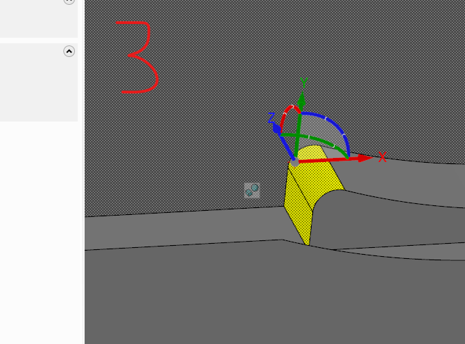
Moving/Rotating Solid Faces - Gnomon Issue
SuperHoneyBadger replied to SuperHoneyBadger's topic in Industrial Forum
Another icon or button that my lizard brain always sees, but has never activated. I always thought that initial activation of a Dynamic Transform was my only chance to move the origin of translation, and felt it was clunky in that regard. This will be a daily driver for me now. Thanks as always! -
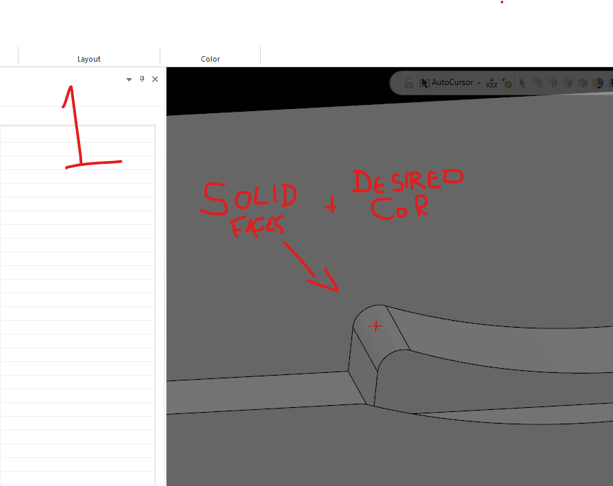
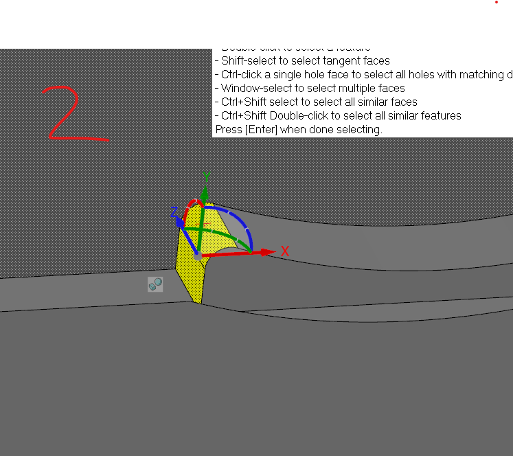
Disclaimer/Info: MC 2022, with a native solid made by extruding wireframes. Using the Move command to select the faces. Trying to use Move to rotate the outer vertical faces of the pocket shown in (fig. 1) to make a little room for the part in the jaw. The corner rads and back face will locate it enough, so I don't want contact on the sides. When I select the faces I want to rotate (fig. 2), I get a gnomon to specify the origin of the transform. Unlike other transforms, the first movement of the grey dot where the axes meet applies a transform op to the faces (fig.3) - I would expect this action to only move the gnomon to my desired center of rotation/transform, and then be able to rotate the selection. Is there a way to move the gnomon to a point without moving my geo? Or are my CAD expectations showing through for this tool?
-
That's a big 10-4. I have MasterCam 2021 and 2022, that's the full kit I can bring to bear on my parts. I hear you guys throw around CAMplete, Verisurf and all those other fancy, book-learnin' programs all the time. I have been operating under the assumption that I am not skilled enough to know that I need them. Without de-railing the thread totally, what is its purpose?
-
Our post outputs this line: G131 (HI-SPEED) We have a misc. value called "Hi-Speed Style", and when it gets set to 1, the post adds the above code on it's own line after the toolchange, and carries on until it's cancelled (every op). Is this naked G131 line the same as G131P1? I'm hoping it is, so I don't have to delve into the post, or even worse - add manual entries for the calls.
-
Are you referring to a page in the machine control here? I'm mostly at the MC seat, so I don't get to poke the buttons on our VX660 too often, and I can't see where these settings would be in MasterCam
-
Hidden/Non-Existant Levels When Opening Old .mcam
SuperHoneyBadger replied to SuperHoneyBadger's topic in Industrial Forum
Fie on you, Lazy Guy! Thanks for the tip, I'll be on the lookout for self-destructive solid bodies. -
Hidden/Non-Existant Levels When Opening Old .mcam
SuperHoneyBadger replied to SuperHoneyBadger's topic in Industrial Forum
"Used or Named" radio button did the trick! Was set to "Named", didn't notice or use those buttons before, thanks a million! Seriously, thanks so much, I have been struggling with this issue constantly as a minor annoyance. Never had a super complex file that I NEEDED the wires from until today. -
At our shop we have 1000's of programs made in earlier versions. Most register as "MastercamX6 Part Files" in explorer. I have only been around for a year, so most of them I have never seen. I can open them in 2021 or 2022 for re-posting or grabbing a setup sheet, no problem. The issues start when I am getting wrist deep and starting modifications/uprev's or trying to make some hi-speed versions. Many, if not all, of the files have the part solid, part wireframes, surfaces, and toolpath driving wireframes completely invisible in the Levels manager. As in the levels don't exist - but I KNOW the geometry exists. Why do I know? Toolpaths are usually fine, and the Chain Manager will show the wireframes as "Chain 1, 2, 3... etc" or whatever it may be when its open. That's the only time I can see these particular wireframes/edges. Is this a common issue when opening older files? My initial thought is that the issue is similar to when you don't name a level, and you can lose the level in the manager, but the geo still exists. Maybe the X6 level naming/numbering system doesn't import well (or I am doing it wrong, by just opening it)? I must confess that 2021 was the first CAM system I have used, so I am totally stabbing in the dark as to how the older versions worked. Any help would be appreciated! And may I say that this forum and its denizens have been an incredible companion as I started, and now continue, learning MC - and develop bitchin' CAM habits in general.
-
See above thread ^^ A veritable wealth of G131 Mats knowledge, helped me figure it out. Happens to be about your very machine. Hope you get it running quick and smooth, my guy!
-
Yes. I don't think MC is set up for GPU compute on toolpath calculations. I could be wrong, but I'd be surprised if true,

