Guess_who
-
Posts
336 -
Joined
-
Last visited
-
Days Won
6
Content Type
Profiles
Forums
Downloads
Store
eMastercam Wiki
Blogs
Gallery
Events
Everything posted by Guess_who
-
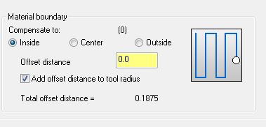
I see. So you're not concerned about the rolling over edges, you are using a contour as a boundary and it's violating. I would guess it's your setting on the cut parameter page. How do you have this area defined? (see attached) Start by putting some values in the offset distance and see if your toolpath starts to pull back from the boundary. In my opinion this material boundary section is buggy. I've had to put strange offset values in here to get my tools off the walls before. I don't know why.
-
Is it rolling edges? Or are you talking about it cutting into the slot area on the right?
-

Can you Post feed rate on every line?
Guess_who replied to nakaroto24's topic in Post Processor Development Forum
As Bryan said, look at the section in your post "pfr" and show us what that looks like. Just curious, but why do you want the federate to post out on every line? -
Sounds like the pcomment section of your post is backwards. here's what it should look like; if gcode$ = 1006, scomm$, e$ if gcode$ = 1005, "(", scomm$, ")", e$ Ours is in the pcomment3 section. gcode$=1006 is when your manual entry is marked as code, and 1005 is marked as comment.
-
You could just send an email to your MasterCam rep. As long as he can reproduce it, then they can track it down. If it's just a once-in-a-while thing, then they have a harder time. Make sure you explain the exact sequences you're using. Also, you may just try a re-install. I had a issue once that I could reproduce, but only on my computer. I fixed it with a re-install.
-
Could be a bug, if you can get it to repeat, they should be able to track that one down pretty fast. Make sure you submit a bug report. Sorry I couldn't help. Good luck.
-
I have never had an issue with X7. I'm not sure what process you follow to select your holes, but when the drill point selection opens up, choose "ENTITIES", then pick your arcs. This works 100% of the time. If you use the icon that looks like a mouse pointer, it is far too easy to pick midpoint, instead of center, and so on. Using entities only allows you to select arcs. Also in your sorting options make sure your don't have "depth filtering" turned on.
-
What Version of MasterCam? is it X7 SP2?
-
Well we don't have an Integrex, we have a Mori NT-3200. Usually we use Esprit to program it, but I thought you might try switching your Continuous Axis support in your machine component manager, to Signed Continuous which should allow your spindle to go past 360.
-
Surface finish contour randomly scaling cuts in X7
Guess_who replied to Kevin Kostiuk's topic in Industrial Forum
I generally like most of the X7 improvements, but "create new tool" is not one of them. I opt to copy an old tool now and modify it rather than going thru the new tool generator. I haven't noticed anything funny about the scaling issue. Yet. -
Well it depends on what you are programming. MasterCam has some pretty nice cycles in multiaxis tool path. I would say a good place to start is pick what type of toolpath you want, like Curve, swarf, flow, ect, then go thru each page of the cycle and look at the help files to learn what every option does. And once you find a cycle you want to use, there are tons of option with-in each cycle to get to the same result. I think most programmers will learn a handful of different techniques and stick with what they've learned. If you're programming using DFO, MasterCam works just great, but I have issues with TCP programming. Our post doesn't post out the correct code for TCP. Also, don't trust "check surfaces" in 5-axis cycles. I have found that once in a while MasterCam will violate your check surfaces. That was in X6, I haven't done anything complicated in X7 yet. If you have a particular 5-axis cycle in mind, I can try to give you some better information.
-
Are you looking for Techniques in MasterCam, or general programming techniques?
-
Can you Post feed rate on every line?
Guess_who replied to nakaroto24's topic in Post Processor Development Forum
This sections in your post change the feed to *feed, an "*" forces output. [b]plinout [/b] #Output to NC of linear movement - feed pcan1, pbld, n$, sgfeed, sgplane, `sgcode, sgabsinc, pccdia, pxout, pyout, pzout, pcout, feed, strcantext, scoolant, e$ [b]pcirout[/b] #Output to NC of circular interpolation pcan1, pbld, n$, `sgfeed, sgplane, sgcode, sgabsinc, pccdia, pxout, pyout, pzout, pcout, parc, feed, strcantext, scoolant, e$ Should look like this when you're done plinout #Output to NC of linear movement - feed pcan1, pbld, n$, sgfeed, sgplane, `sgcode, sgabsinc, pccdia, pxout, pyout, pzout, pcout, *feed, strcantext, scoolant, e$ pcirout #Output to NC of circular interpolation pcan1, pbld, n$, `sgfeed, sgplane, sgcode, sgabsinc, pccdia, pxout, pyout, pzout, pcout, parc, *feed, strcantext, scoolant, e$ -
We have a ton we use. Here is a small list of the macros that are in every Mill on the floor macros.pdf
-
As a general rule, we use TOP for our WCS all the time. And use the T/C plane for rotations. What rotations are allowed will be defined in your machine definition.
-
Shifting a program on a Haas without using the offset table
Guess_who replied to Thad's topic in Industrial Forum
Or you can use G10 G90 G10 L2 P1 X0 Y0 Z0 B0 - will set you G54 (P1) X, Y, Z, and B to zero. The G90 sets it as an absolute value. Or if you do a G91 G10 L2 P1 X.005 Y0 Z0 B0, that will incrementally move your G54 -X- +.005 But what we would do here to blend multiple tools, is just use the Tool offsets. Ray -
Yes, we had the stand alone version to. Give them a call. They hooked us up with 3 seats for 30 days for testing. Good customer service. The software is very nice. I figured there would be more soon, but when we tested it, there was only the Haas post available. But we tested right during the first release of X7, so there really wasn't much in the way of information available. We are still considering what is best for us. I like the fact that your probe code is nested into you MasterCam operations, but I didn't like that I couldn't pick points on a surface like you can with the standalone. For example, if you wanted to probe a -Z- surface, lets say, in the MasterCams version you have to construct a point and project it onto the surface, then choose that point, while in the Renishaws version you can just click anywhere on the surface without constructing geometry. Ray
-
We had a 30 day trial of it. Nice software. It basically works very similar to Renishaw stand alone. One issue with the MasterCam version is that there is only one post that supports it so far. Call your dealer and get a trial version and check it out. We are still shopping. I think we may just go with the stand alone Renishaw version, but we everything is still up in the air. Ray
-
Hopefully a bug and not something that CNC decided to remove.
-
Reverse Depth Cuts: How do you pull this off now?
Guess_who replied to huskermcdoogle's topic in Industrial Forum
I know this is an old thread, but I was just going to ask the same thing. Seems like a very simple improvement that MasterCam could do with a simple toggle "cut bottom to top" or something like that. I would love to see something like this added. -
Yes, I use it. And it works for most things. Just not when using the trimming function. Not a big deal. Thanks for the reply.
-
Well whenever I have said I'm sure about something, someone else has proved me wrong. But, as far as I know, yes, I am using it correctly. Pretty simple actually, click "mask only", then choose just points. Pick trim, and hover over your solid. You will be able to pick any solid edge of the part, whether its a line or arc or whatever. I will agree that masking works with most functions, but Masking + trimming, just doesn't work with solids edges.
-
Thanks Colin, but that doesn't seem to work for solid edges when you're trimming. IDK why. But thanks for the tip about the quick masking. I never really used them, but that seems like a handy feature.
-
Great I'll try to get into the habit of Alt-S. BTW - doesn't the default seem backwards? I might actually want to trim to a solid edge once in a blue moon, but not very often. Maybe I am just used to doing things the old fashion way and I need to modify how I use my solid edges. I've tried using solid edges for chaining, but it's just more of a hassle than it's worth IMO.
-
I would just like to complain for a minute. But can anyone explain why when you choose "trim", MasterCam defaults to solid edges instead of 2d geometry. when I go to trim 2d geometry and there is a solid under it, MasterCam will always choose the solid edge line first. Is it just me that sees this as annoying and useless? I know, "just turn off the solid geometry level", well that all find and dandy when you have a simple solid. But when you have a very complex solid, it takes a while to turn it on and off. And when you have to do it 100 times, those seconds add up. Where is the option to say "ignore" solid edges. And BTW - masking only 2d geometry doesn't work. In my screen shot, here is an example of what I'm talking about. If you try to trim the dark blue line, to the green line, MasterCam will choose the solid edge of the light blue pocket. If anyone has some config settings or something, I'd love to try it. OK, I'm done complain. thanks for listening.