Aaron Eberhard
-
Posts
1,419 -
Joined
-
Last visited
-
Days Won
104
Content Type
Profiles
Forums
Downloads
Store
eMastercam Wiki
Blogs
Gallery
Events
Everything posted by Aaron Eberhard
-
My guess is because your stock is hollow, so after the first pass it's free to move through it: If you go back to OP18 and right click > Mill Toolpaths > Convert Stock to Mesh, then, edit Op #19 and choose that mesh instead of the one you have chosen, you'll get this result: Edit > Looks like you figured it out by the time I got 2023 fired up
-

Force tool change not working correctly?
Aaron Eberhard replied to Radical1's topic in Industrial Forum
No idea. I can replicate it. If you put a Contour or something that uses the more modern interface, it works correctly. I'd send it into [email protected] or via your reseller. -
I often toss the dxf or solid on my other monitor and slap the drafting dimensions on it. it takes about the same amount of time as cleaning up the geometry, and then I can make a geometrically simple model instead of dealing with whatever fillets or weird shapes I sometimes find in MFG models. 6 of one, 1/2 dozen of another...
-
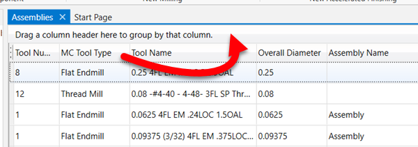
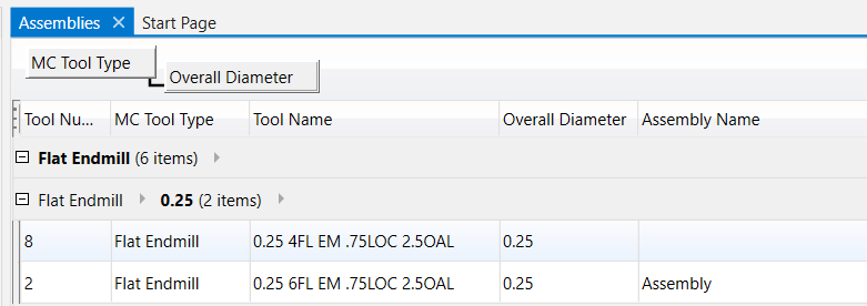
Drag and drop the column header to where it says "Drag a column header here to group by that column". You can do it multiple times:
-
I'd do the larger "Corner" ones first, then the lower ones. Both might need to be Variable:

-
Using ribbon hotkeys makes MC sluggish
Aaron Eberhard replied to cbarton's topic in Industrial Forum
The best bet is to email [email protected] with a repeatable set of steps to reproduce the problem. -
Milling on Okuma LB3000 EXII using Mastercam code
Aaron Eberhard replied to Minus 40's topic in Industrial Forum
Seriously?! Who integrates anything onto a CNC and doesn't give you an M code to drive it? -
That's how I do it, except I have my "Vector Manufacturing" folder with my tools, and I make a tool library for all of my customers that contains the tools they have. Management is a bit of an issue, but I like knowing that I can trust they already have a tool I've used before with them. I also make a separate tool library for holders if that's prudent, for example, if I'm tooling up a big job that I know we're using SST or Haimer or whatever, I'll make a Haimer HSK-63A tool library that I can then always reference when programming with those holders. A lot of people don't know that you can open two tool libraries in the Manager and then drag and drop into assemblies directly from another library.
-
Milling on Okuma LB3000 EXII using Mastercam code
Aaron Eberhard replied to Minus 40's topic in Industrial Forum
Whenever you feel bad about buying Fanuc options, remember there's a poor Okuma guy somewhere who didn't get negative tool comp.... -
My favorite is when the alloy of this order isn't exactly the same, so all of that painstaking work you did optimizing the cut times on the first lot of material when you first ran the job no longer applies, and your tool life is like 50% of what it was previously!
-
Thanks! I was joking above, but I believe you're the first subscriber I just created this channel a week or two ago, as a friend was running into trouble figuring out an old Robodrill they bought. I figured I'd document my adventures in mine. Mastercam help seemed like it fit as well.
-
Sorry about the delay, I just now got a chance to play with it. Here's a video showing how I did it: I feel like I should put a Like and Subscribe and a Patreon plug in there
- 23 replies
-
- 11
-

-

-
Ah, that's unfortunate. Good on you for trying it, though!
-
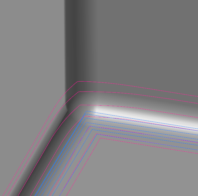
Yeah, Dylan is on the right track there, and the closer the radius is to the tool radius, the more jankiness you're going to encounter, as any minor changes to the tilt will cause the center/tip of the tool (where the blue backplot lines are showing) to visually look worse. I'm very excited about displaying the contact point in backplot, and I've been enjoying it in Simulator. For the screenshots above, here's what the contact points look like vs. the backplot: I could easily do an entire 5 day class just on just Unified/Swarf/Pocket. I've done a few 3 day classes focused on just Unified and digging into this stuff, and it's always so well received.
-
Thanks guys, just trying my best to make the world a better place and everyone who wants to learn a bit more knowledgeable!
-
I'll try to find some time today or tomorrow for ya.
-
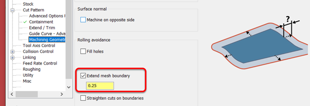
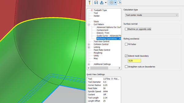
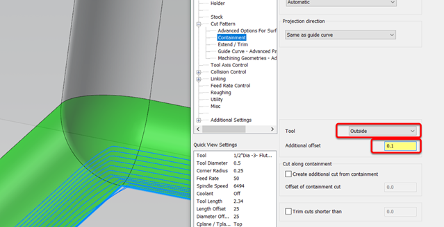
Ah, sorry, I missed that the side extension was essential. It's definitely not as easy as the surface-based toolpaths to do it with the geodesic engine, and you don't have a Top/Bottom extension, you can only do a blanket extension. It's not too hard, but you need a bit of background knowledge to really leverage it. Skip the next paragraph if you don't care about the mechanics of it One important note is that I'd recommend using this with a single Guide chain (Parallel equivalent), as having two that it's trying to Morph between can get a little weird sometimes. Geodesic engines are based on the mesh (they create a mesh in the background from your selected surfaces at whatever tolerance you specify). The edges of the mesh are considered a constraint that it has to stay within, using whatever pattern you wanted it to fit. So, you have two problems to solve: * One is that your mesh (the fillet) doesn't extend at all * Two is that your containment is based on the original mesh. To solve the first problem, use Cut parameters > Machining Geometry Advanced Params > Extend Mesh: You can preview the toolpath, but nothing will change at this point (other than taking longer to generate!): But, in the background, the mesh has been extended on all sides. So, to solve Problem Two, can be solved using Cut Pattern > Containment, and allowing the tool to go outside the containment: Other than that, I think you'd probably have to create the geometry you want to.
-
All that time is really just to ensure they know how to properly export models to screw the programmers in the especially debilitating way...
-
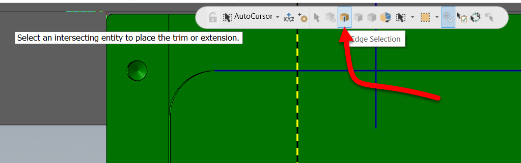
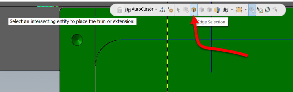
Ah, I think you're talking about Edge Selection:
-
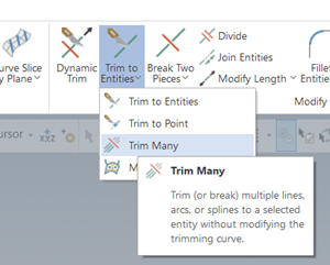
Are you talking about "Trim Many"?
-
Tl;dr - Cut Pattern > Style to Guide instead of Parallel, or, Advanced Options for Surface Quality > Method > Exact instead of Approximate. ---------------------------- The reason for this is the collapse of the pattern due to your tool axis control. If you turn off collision control and set the Tool Axis Control back to "surface", here's what the "raw" Parallel toolpath looks like: When you turn on Tool Axis Control set to Fixed Angle to Axis (good call, BTW), it keeps all of these passes, but it's now trying to keep the same surface contact point with the new tool position. Since the toolpath is set to Center/Tip, it looks worse than it would if you could see the contact point, but that's still a really fine stepover for a fillet at the bottom. The changes I would make: Change the pattern type to (2) Guides instead of Parallel. That'll let the toolpath blend between the top and bottom better and you can benefit from Machining Geometry > Calculation Type > Tool-Center Mode (the default), where it's smart enough to calculate it based on the tool center. It gets rid of the gouging/fishtailing you have on the corner as well. When your fillet is almost the same size as the tool like it is in this case, I'd recommend tightening up the Cut Tolerance, maybe .0001 instead of the default .001? I'd also change your Collision Control to tilt to avoid the walls unless you have a specific reason to ask it to retract if it gets close to the wall? I think you'd prefer to have it tilt away. You probably don't need to use the second collision control.
- 14 replies
-
- 10
-
-
-
Taught by the best!
-
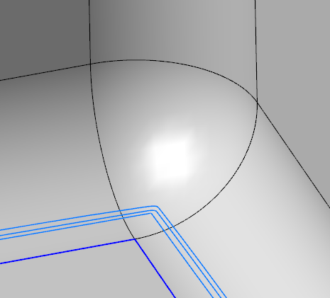
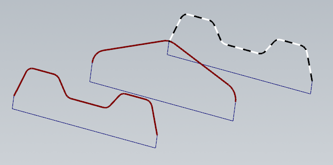
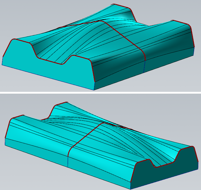
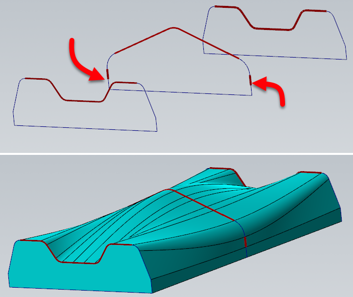
Yours shows the problem on the opposite corner.. Branch only syncs the one start point unfortunately. Reko - What I would recommend doing is using Sync By Entity, but to make that work, you'll need each chain to have the same number of pieces. In this case, the easy button is to leave the three pieces of the square bottom alone so they sync up nicely, and use Wireframe > Curves > Curves from Splines to stitch the rest together: That'll keep the sharp edges on the bottom: he trickier way to do it is to control the sync points if you don't like the results, but be careful, as each of the chains need to have the same sync points, something like this: Here I wanted it to sync up the radii in the corners, and maintain that sweep, so I had to break the verticals so that the "flats" on the side had somewhere to sync up to. I think the results are better, but your mileage may vary. Obviously, you could continue this concept and manage the sync of the bulge in the middle to stretch out to the corners, something like this: And yes, I've spent WAAAAYYYYYY too much of my life working with surface sync points!
-
You would likely benefit from some instruction from your reseller. Barring that, sounds like this would be a great time to post a file and ask for assistance from this awesome community
-
Out of the box, you're not going to get that level of intelligence. You would need a custom add on written to take that surface area of your engagement into account and create your passes that way. The same problem exists in thread milling & full engagement t-slotting, but normally it's not a enough deal so the easy solution is just to create two or three toolpaths with different rough & finish parameters, but you'd have to calculate the amount yourself. With a T/slot or thread-mill, though, the variation is generally not so large that it really matters. Your reseller should be able to help you out, or you can reach out to Byte on here (https://theebyte.com/), or give me a shout as I have some resources that do custom add ins as well.