Aaron Eberhard
-
Posts
1,406 -
Joined
-
Last visited
-
Days Won
103
Content Type
Profiles
Forums
Downloads
Store
eMastercam Wiki
Blogs
Gallery
Events
Everything posted by Aaron Eberhard
-
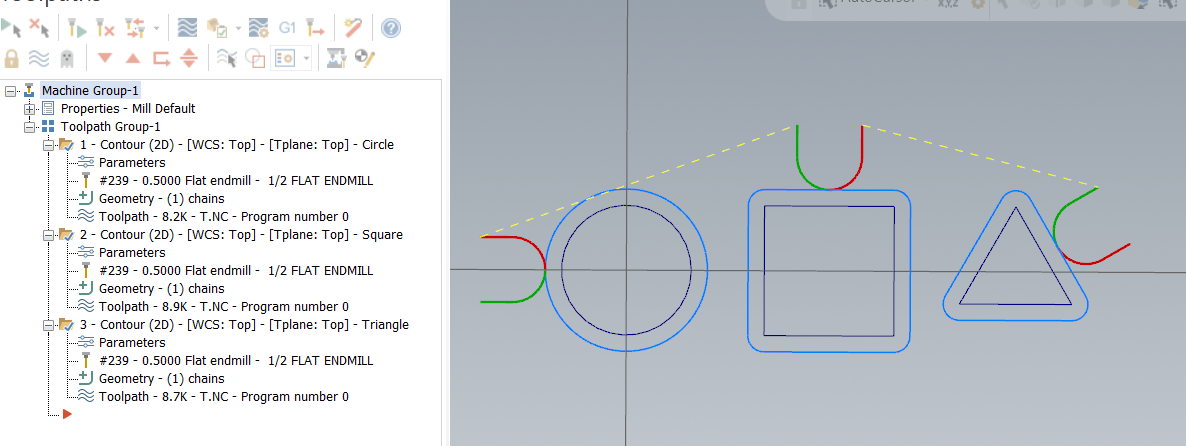
In general, to make a multiaxis pocket work, you just need a single floor surface (so you'll choose the bottom of one of your pockets), and a containment/wall surface(s). To make it work really well, you'll ideally have a volume to remove (such as a stock model), so it knows how high to start if it's above the walls for any reason, but it looks like your pockets are all pretty uniform depth, so you probably don't need to have a stock model there.
-
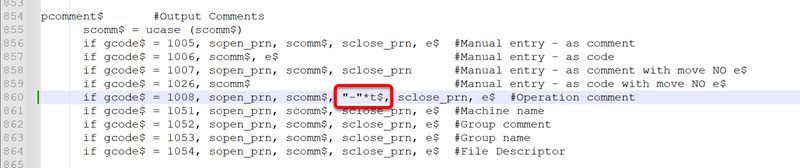
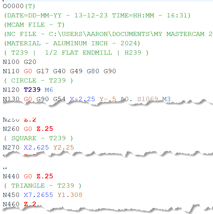
So, one thing to note is if you can't use "force tool change" for whatever reason, but you wanted to modify your post output so that it's still calling Txx m6, some machines will interpret that as a "send tool home." Basically, between each toolpath it'll take a trip to the tool change position then immediately jump back into action... It's like "force tool change" with none of the benefits of being able to easily resume mid-program (unless your control has a nice resume function that scans for and implements all of your conditions). If you just called out a Txxx without the M6, you might cancel a tool pre-stage which would be inefficient for the next tool change. I'm not sure what happens in that case. As above, I'd recommend doing it as a comment. You can have the post automatically put it in, though. I'm not a post expert by any means, but if you have a default mp post, I think you can just modify it like this: (If it's blurry, I found the Operation Comment line, and added a "-"*t$, before the close parenthesis). That gives me this output:

-
Yeah, I reported this back when I was on the inside, too, but I couldn't figure out the steps to reproduce it from scratch. That's the big difference now, I think. I dunno, we'll see
-
Laptops are always hard, as even if you get a blazing fast one, it can be hampered by cooling issues that cause the clock speed to get pulled way down. I got a i9 laptop with an awesome graphics card when I got started from a friend at the beginning of last year. It was great until it has been crunching for 4-5 minutes, then everything slowed to a crawl. Try regenerating your area rest toolpath, and watch your processor and ram temperature. I found that it was totally useable with a simple cooling stand (https://www.amazon.com/gp/product/B01MRWE5AX) or "air vacuum" (https://www.amazon.com/gp/product/B01G3G3C7M) . When I got my laptop in, though, it solved all the issues by being a workstation, not an office/exec portable chassis with no cooling. It's definitely bigger and heavier, though! The most recent thread I know of about this was from Jake L: I know he'd be happy to talk to you about what he just got.
-
Nope: Note: different random file, so the # count is different than the part from yesterday
-
Yeah, I ran it up the flagpole yesterday, I know that the Product Owner in charge of that area is acutely aware of it, and it's piled on top of the previous defect which gives it a decent bit of gravitas. Great thinking on putting the two together!
-
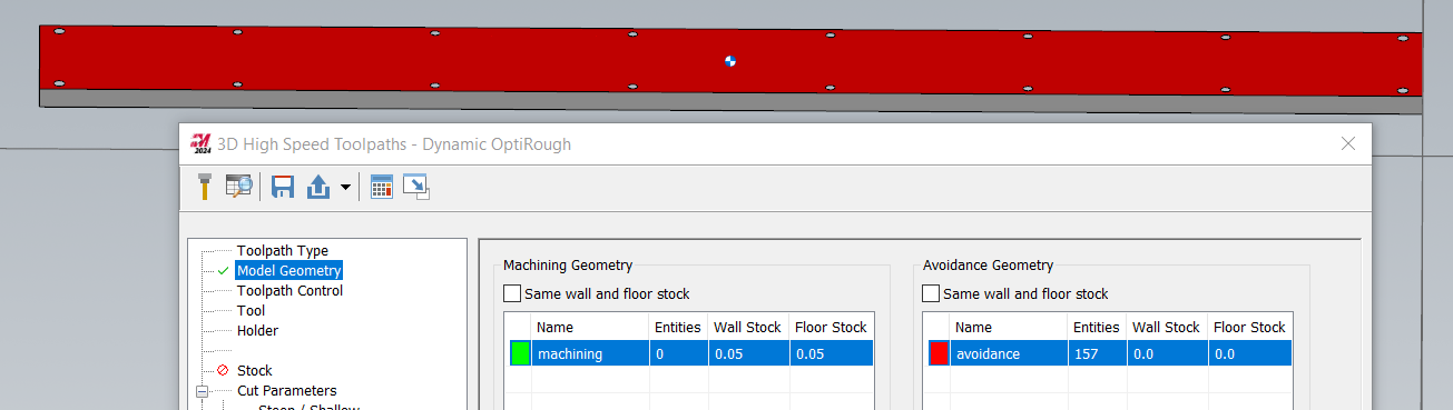
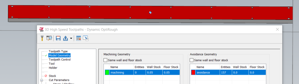
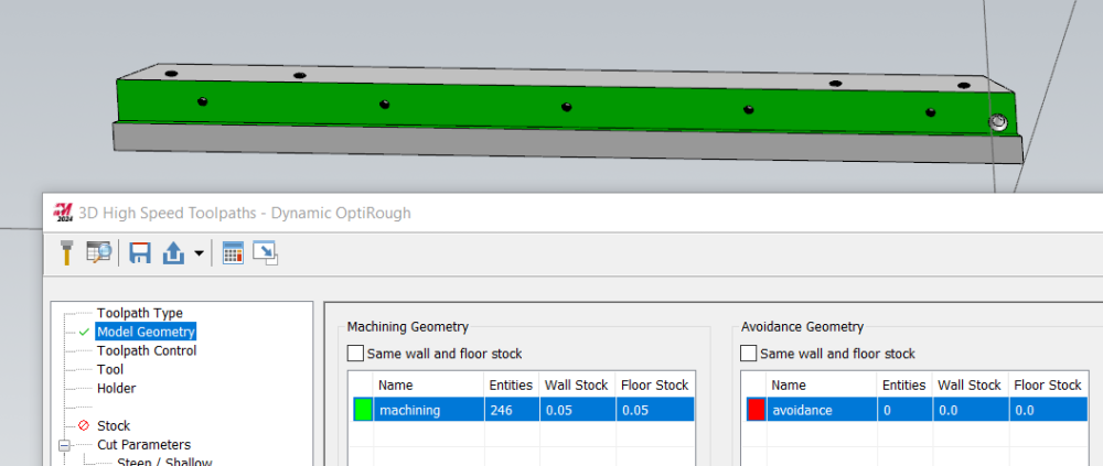
Good call, I've had the same thing but didn't put it together! Time for a test! Yeeeeuppp. . I'm not a matham.. mathimat... . Mathin' Guy, but I don't think this looks like 245 faces selected: This was open whatever step I had laying around, dynamic transform, dynamic transform, select faces. Great thinking TFarrell! --------- Further Edit: If you add it as the Machining group, it'll clean itself up when you green check out. If you add it as the Avoidance, it'll stay broken until you save the file.
-

Facing to OD transition, and Partoff paths
Aaron Eberhard replied to Terminus-Est's topic in Industrial Forum
Agreed with TFarrell9. It sounds like you want a Finish toolpath, not a Facing toolpath. Facing is for exactly what it says. If you're trying to follow a contour around the corner, you should use a Finish toolpath. -
Hidden entities/models when generating Stock Model
Aaron Eberhard replied to Tinger's topic in Industrial Forum
Yep, as TFarrell9 mentioned, this is a common problem. I worked with Curtiss @ Mastercam's QC department recently to pin down exactly what causes it and get it logged as D-48731. The trick is a second Dynamic Transform after you import solid models. In your case, you imported the vise into your file. If you had done a dynamic transform right then, it wouldn't have happened. But, after accepting the import, Dynamic Transform again. For some reason, this now flags the solids onscreen as part of the stock model. As mentioned, the solution is to just save the file, possibly reopening it. I can't remember if you need to reopen it off the top of my head? That forces it to go through all of the solids association, realize there's a problem with that stock model referencing solids that aren't supposed to be included and then dirtying it. When it's regened, it'll be fine. There's no need to export/mesh/delete/anything else. That'll fix ya up. -
You're welcome It can go back and forth (I think he has some videos up on how it works), but I honestly don't use it much.. In my case, I can manage everything I want via Mastercam, so I just use the desktop version and enter values as appropriate into the toolpaths. This is a prime example of where you might have the same tool but specific settings (stepover/DOC/etc.) for this one toolpath.
-
I promise that you will save more in than the $195 lifetime price on in the first month in cycle time & tool life if you're programming every day. Every month after that is pure profit. It's awesome. It was one of the first purchases I made when heading out on my own. It lets me start from VERY good feeds and speeds in pretty much every situation. Eldar is awesome, tell him I said hi For example, let's say this part is 6061-T6, and you're trying to figure out how different roughing strategies would work on this part. Let's assume that you're cutting a .5"thick piece down to leave a .075 floor (removing .425"). Remember that we have no clue what the real sizes of the part are For a .375" 3FL Endmill w/ .625LOC and .75" Stickout, in full attack mode (100%), HSM advisor recommends 63.3% stepover (.2373) for a Dynamic path, 102.73 IPM/13409RPM (.00255 FPT, 1316SFM). It doesn't know that it's thin-floor, of course, but it says that it will be putting 66 lb of cutting force into it (using 2.6HP). Now, we know that's way too much, if you took the part out and applied 66lb of force there, you'd bend it quickly. Taking the same exact everything with a .25" Endmill recommends a 31.6% stepover (.079"), 133.5IPM/23798RPM, which = 24lb of force. Getting closer! 50% of feed & speed equals 12.1 lb of force, etc. No matter you scale it, a .25 endmill is putting a lot of force into something you can probably bend with 2 to 3 lb of pressure, right? A .125" Endmill goes to 5.4% (.0068), 559IPM/98147RPM which would equal 4.2lb. Now, my machine won't go to 98k! So if I type in my max in this scenario, let's say 10,000 RPM, which is 10% of its recommended value for this cut, that slows it down to 5.7IPM, but it's only putting .42 lb of force into the cut. That could work!
-
Don't forget that Dynamic roughing can really be used effectively to control the amount of stress put into the part. If you use HSM advisor or equivalent, play with the stepover numbers until you get a minimum of cutting force, and leave just enough for a skim pass if you would prefer a different finish on the floor. Take that with both of pieces of advice above, small tools impart less cutting force than large ones, and I've used double-sided tape under thin floor areas to help squash vibration. Stress-relief is a good idea if it's a high tolerance thing, rough it out, release all clamps, secure it for finish pass. It's hard to give more specific feedback without knowing materials, sizes, tolerances, etc.
-
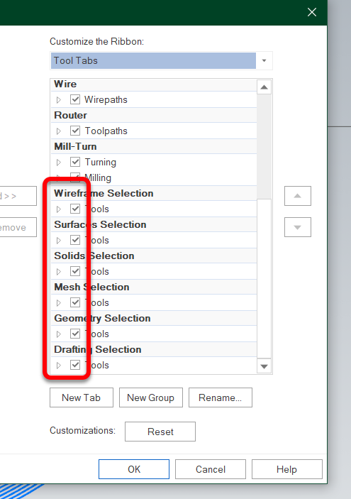
I think you need to turn them all off under Options/Customize the Ribbon:
- 1 reply
-
- 2
-

-

-
AI High Speed Look Ahead parameter settings
Aaron Eberhard replied to JSwistak's topic in Industrial Forum
Yeah... I wish there was a jaw-drop emoji. -
Multi-Path Controls or Multi-Task Machining
Aaron Eberhard replied to jmoore3's topic in Industrial Forum
I'd highly recommend you talk to your reseller and ask for a demo for your machine (or whatever similar model they have handy). They should be able to show you exactly how to go through the process to get code to run on the control. -
Saving as iges file flips surface normals
Aaron Eberhard replied to MIL-TFP-41's topic in Industrial Forum
Yeah, it's been a while since I've had to deal with iguess, which is great for me. Sorry you're suffering, though! It's been even longer since I looked at the spec, but if I recall, the iguess surface normal is simply determined by which "direction" the surface is described in (i.e., is it going left to right or right to left kinda thing). You can see the same thing if you create this as a revolved surface in Mastercam: That said, I'd recommend revolving this as a surface, then you can use Surface > Normals > Orient to quickly align them. Since they're native surfaces, the normal will survive the export to iges (see attached file). The problem you have otherwise is you're always going through the parasolids kernel for surface manipulation, whereas if you deal directly with native surfaces the whole time you avoid conversion. You can see the difference in file size if you Save As this solid as an iguess, it'll be ~500kb. If you save a revolved surface as the same, it'll be 20kb. surfaces.igs
-
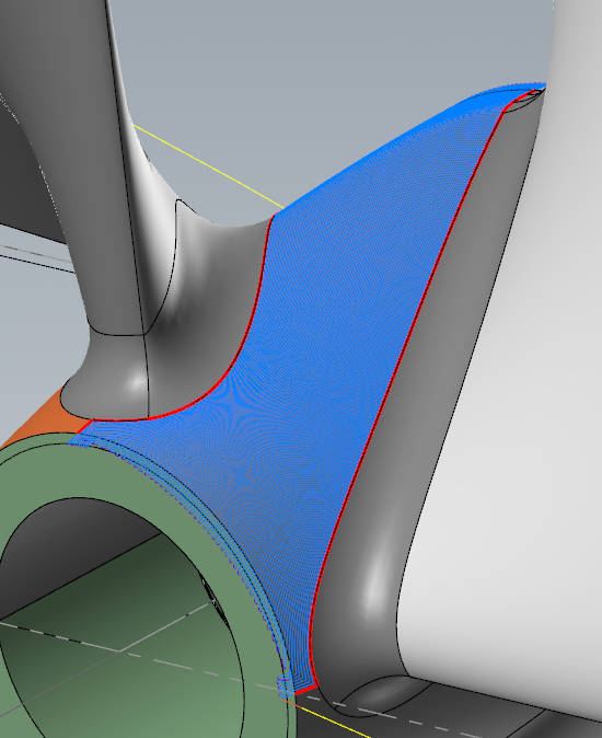
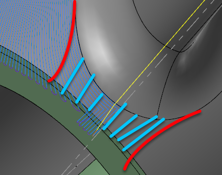
Take a look at this and see if it'll work better for you. I didn't have much time here between meetings with customers, but I slapped a Unified > Morph on it (Guides would give you approximately the same results). I turned on Smooth corners (so it doesn't do a 90° bend in the corners) and I also extended it. Also, I changed your linking to be a blend in small gaps, so it transitions nicely instead of "direct." The only other change is Op2 is the same as Op1, but I put on collision control for you so it won't gouge the blades.Sample - Unified.zip One other thing you can do is get fancy with trimming the "corners" to make the toolpath smoother, and then do a small toolpath in front of the impellers, something like this: I didn't have time to play that much and I didn't want to leave you hanging until this afternoon when I would have had a chance to do it.
- 9 replies
-
- 18
-
-
-
I'll try to take a look at this after some meetings this morning.
-
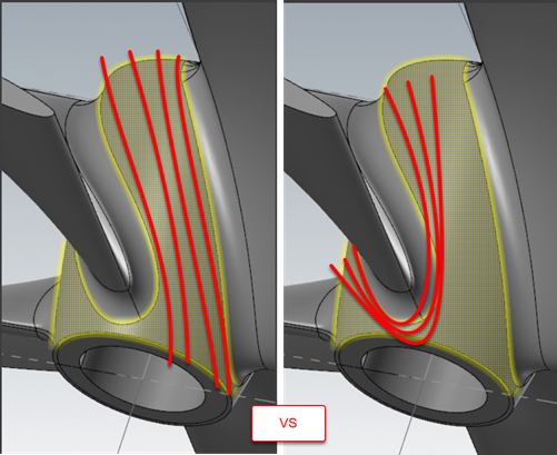
Also, what pattern are you really looking for? Do you want to do that entire hub area highlighted in the first pic? You'll have better luck doing each "side" of the blade as one toolpath, otherwise you're going to have a LOT of wasted time and a super-smooth polished look where you have to run over the area in front of the blade a bunch of times: In that case, I'd split the hub surface up into two.
-
Just choose two curves in Unified and choose Morph as the pattern for it. Any chance you can post a file?
-
You're welcome, I'm happy to be a rubber duck https://en.wikipedia.org/wiki/Rubber_duck_debugging
-
With tool break detection, is it necessary to do it as a drill cycle? I mean, if you're okay with it happening as a standalone toolpath anyway, just do it as a manual entry. The big benefit to doing a custom drill cycle is it allows you transfer positional information to whatever you're trying to do (i.e., Probe at this XYZ), which seems unnecessary for a tool break cycle? Or am I missing something?
-
Dunno... It was just the most family appropriate thing that I'd expect them to be spamming. That whole crypo currency thing seems to be the midst of a collapse. It looks like you're not qualified to run a crypto company unless you have at least two felonies to your name nowadays
-
I dunno.. He seems legit. I'd buy bitcoin from him...
-
5 axis curve toolpath feed plane
Aaron Eberhard replied to Metals and materials's topic in Industrial Forum
Any chance you can post an example and we can help you directly?