Aaron Eberhard
-
Posts
1,406 -
Joined
-
Last visited
-
Days Won
103
Content Type
Profiles
Forums
Downloads
Store
eMastercam Wiki
Blogs
Gallery
Events
Everything posted by Aaron Eberhard
-
Are you sure that machine def/post is 2023? Make sure to enable all previous versions. For example, the two under your circled file are X9 files. 2024 won't update those.
-

Toolpath Transform
Aaron Eberhard replied to poolrod2's topic in Machining, Tools, Cutting & Probing
Sorry Rekd! I just saw this. I'm not really sure, to be honest.. I never use it. I just know that I've been bitten by it. I'm assuming it exists so you can do all sorts of fancy tricks with the post about repositioning and rerunning code or something, but I've never had a need for it. Maybe someone else knows the use case? -
EDIT: I think I mis-read your original question.. I thought you were trying to access the files stored on the DS for sub/macro kinda stuff.. On a second read, I think you're just trying to load them. Apologies. On the Kitamura it was as simple as going to Program > File Dir > DS, then selecting the program (e.g., o2 [Down arrow]). ----------------------------------------------- I'm not 100% sure if it's the same, but I just did a turn key on a Kitamura, and to use the files stored on the data server I had call them by name using M98, not with the M198 like I was accustomed to. It didn't matter if I had the main program stored locally or right next to it on the data server. To call the sub program (e.g., O0002), I formatted it like this: M98 <O0002>, D0; (note that it is D is the device you're calling out, so it may be a D2, D3, etc., on your machine). Someone who is more knowledgeable in the ways of Fanuc might be able to tell ya why I had to do that, but I'm just writing it off as the machine tool guys didn't buy the 'normal' option
-
Toolpath Transform
Aaron Eberhard replied to poolrod2's topic in Machining, Tools, Cutting & Probing
Specifically, you were "including origin" under Method, so basically, with every transform you were also including resetting your WCS to that particular transform. -
No, it's not your floor surface, something else is going on. Either your stock is wildly big, you've selected the whole model as your drive, etc... Without seeing a file, I'm going to guess you'll be good if you define the Cut Pattern > Containment into your slot. I think it's taking what you've given it and going against a large stock in the background so it's "helpfully" removing it.
-
You revived a 3 year old thread for that? I wish I had as much spare time as you do....
-
Mastercam 2024 and toolpath organization
Aaron Eberhard replied to rgrin's topic in Industrial Forum
From the screenshots you posted, great job on getting organized! You're way ahead of most files that I see! There's some things to like in 2023/4 machine setup, but a LOT to not like. I'm guessing in a few more years it'll be quite useful, but right now it's cumbersome. The fixtures in particular is painful because they're of literally no use if you ever do more than one op in the file. I teach an Intro to Mastercam class, and trying to explain multiple setups now is horrible. None of them understand it because there's no reason! It used to be simple, "just jump into config and change the "fixtures" checkbox." Now (especially on the school computers), it's a 5 minute process by the time the whole tab system loads and unloads, then you add/remove/etc. your new fixtures after deleting the old one.. Ugh. One thing that is nice in the newer versions, though, is if you select a stock model as the first toolpath in your selection for Verify, it will automagically use that stock model as the stock, not the original one. Nice improvement there! Rant over, as far as toolpath organization, I generally prefer to group by tool, with as descriptive of a note as possible, but that gives me the flexibilty to make more groups down the line if I have to reuse that tool for something: Note the "generally" above, though, sometimes it makes more sense to group by feature or whatever else is logical. I just want to know that in a year when I need to revisit this file, I can find what I need in less than 2 or 3 minutes. The important thing to establishing any form of "Structure" here is to recognize that the real world is messy, and sometimes adjustments need made. You're a professional, trust yourself to know when to stay inside the lines and when to color outside of them
-
Suggestions for milling Titanium
Aaron Eberhard replied to Metals and materials's topic in Industrial Forum
Here ya go: I used https://www.kennametalnovo.com/app/en/search/kennametal/productdetail/6167540/full a .75" 13FL R.015 EM w/ 1.5DOC, put into a SST Shrink holder. We were on a Makino DA300 with an HSK-63A that we were specifically told to not exceed 30%(If I recall correctly?) spindle load due to the bearings. A full (1.5") DOC,, we ended up at 1.5% stepover, .0048 FPT @475 SFM (174IPM @ 2419). It was fun. -
Suggestions for milling Titanium
Aaron Eberhard replied to Metals and materials's topic in Industrial Forum
I did a project using a Kennametal RSM cutter for roughing. It was a .75" I believe with 13(?) Flutes? It was insane. And it lasted forever. I'll grab the model number, speeds and feeds next time I'm near a computer for you. It was awesome. -
3D Printing..What are you doing and/or using?
Aaron Eberhard replied to JParis's topic in 3D Printing
I'm just getting started on my journey here at Vector.. I picked up a pretty heavily modified Creality from a friend that already had all the goodies done to it (rails, upgraded grantry, extruder, bed, etc., etc.). I've been using it for rapid prototyping fixtures to proof concepts for customers. It's been very handy. Also handy to have around the house to fix random bits that break (washing machine knob), or make halloween costume parts -
Well, I guess we know who's responsible then...
-
Solid Model Toolpaths and chaining
Aaron Eberhard replied to CoonDogWillie's topic in Industrial Forum
Nothing wrong with using the Contour toolpath here, you're wanting to follow a contour. The big thing I'd change is to put a Sweep on your lead in so it swings into the cut instead of plunging in: Use Entry Point isn't going to do anything for ya since you don't have a point selected before your curve. You can uncheck it. As far as training goes, for free you can get In-House Solutions great guides: https://www.inhousesolutions.com/resource/mastercam-2024-training-links/ There's probably a class at a local community college, or from your reseller. I teach a local tech school, for example.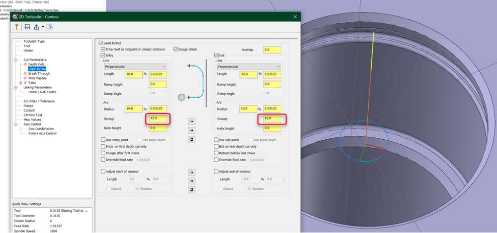
-
Yeah, Eldar is genius behind HSM works. In my opinion-based rating, HSM is world ahead of GWizard, at least it was when I evaluated it a while ago. And the problem with surveys like this is: How did you reach your test audience? Is the survey you're hearing about representative of people who still have a land-line and answer an unknown number's call? Yes? Well, then, I'm questioning the results...
-
Agreed. I'm rocking a 5000, and it's superb. I'd imagine the 4000 is totally fine.
-
How to smoothen this surface?
Aaron Eberhard replied to Metals and materials's topic in Industrial Forum
Exactly. Waterline will do a constant Z step down. Where it's shallow, that'll lead to a large step over. Equal Scallop will give a much better finish. -
I just sent you a PM. If it doesn't come through, feel free to email me @ [email protected]
-
C axis dynamic mill in a Mazak Mill-Turn
Aaron Eberhard replied to Vault's topic in Machining, Tools, Cutting & Probing
Here ya go. It'll be a bit before YouTube updates the quality, but this will show you how to do it: -
Jake - Feel free to give me a call, as this sort of thing is easier to explain on the phone, but basically, it's really hard to create a perfect toolpath that will utilize 100% of all available processors. Really hard. Keep in mind that a highway at 100% utilization is a grid-lock.... Stock models are a great example of something that can't really be multithreaded effectively. You have to take one toolpath and step through it to see material removed. One step at at time. There are some tricks being played when there's logical sections that can be established, but you always have to balance something like that with how much effort to spend pre-processing to see what can be split up vs. just getting through the work. At the end of the day, clock speed is still king for a lot of this sort of stuff.
-
C axis dynamic mill in a Mazak Mill-Turn
Aaron Eberhard replied to Vault's topic in Machining, Tools, Cutting & Probing
Looks like you can do fit a 3/8 endmill in there closer to the wall size with a custom floor, I'll whip together a more advanced video for ya in a few. -
C axis dynamic mill in a Mazak Mill-Turn
Aaron Eberhard replied to Vault's topic in Machining, Tools, Cutting & Probing
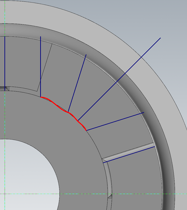
Sorry, just had a moment of free time here. Yep, you got it. The Pocketing toolpath works by being normal to the floor surface at the centerline of the tool, which in this case will leave material in the edges: The only solution to this would either be to do a swarf toolpath or, to create a floor surface that is bent with how you want the tool to bend. In this case, your slot is too small to smoothly transition between sides with this type of toolpath. If you were to do that, you'd need to create a spline at the bottom of the floor that lined up with the lines offset from the wall by the radius .25. It would look like this: Either way, you can use the Pocketing toolpath to do a rest finishing operation. I put a video up here: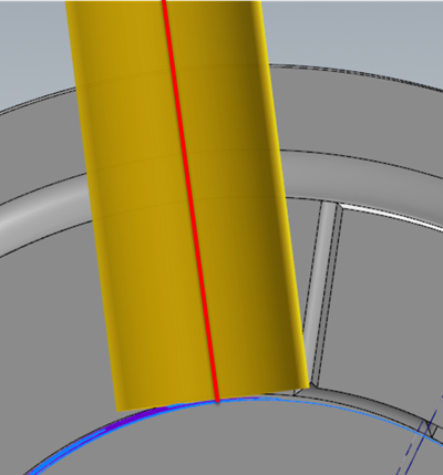
-
C axis dynamic mill in a Mazak Mill-Turn
Aaron Eberhard replied to Vault's topic in Machining, Tools, Cutting & Probing
Yeah, you can do it pretty easily with Multiaxis Pocket, you just have to give it a floor and a stock. I created a stock model from from Op# 2 (Lathe Roughing), then made sure to point the Pocketing op at it. I used an extruded circle as my floor (create a circle, Surface > Extrude), and just selected the entire model as my drive geometry. It gave me this: You can check out the file here: https://vectormfg-my.sharepoint.com/:u:/g/personal/aeberhard_vector-mfg_com/EVI_Nbbq4ZRIrd0zDqL8FUcBZV8zKbs8z5zUXgOnVyXKtQ?e=qHhtmh (I'm almost out of space here on e-mastercam). Let me know if you'd like me to make a video on it. I've been avoiding going out in the rain this morning, but it's soccer time now so it'll have to be a bit later Cheers,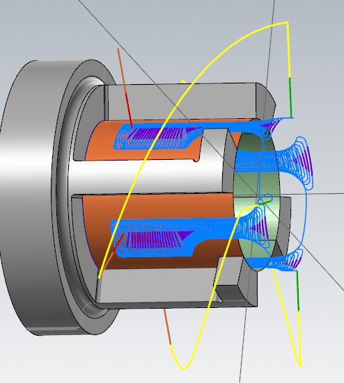
-
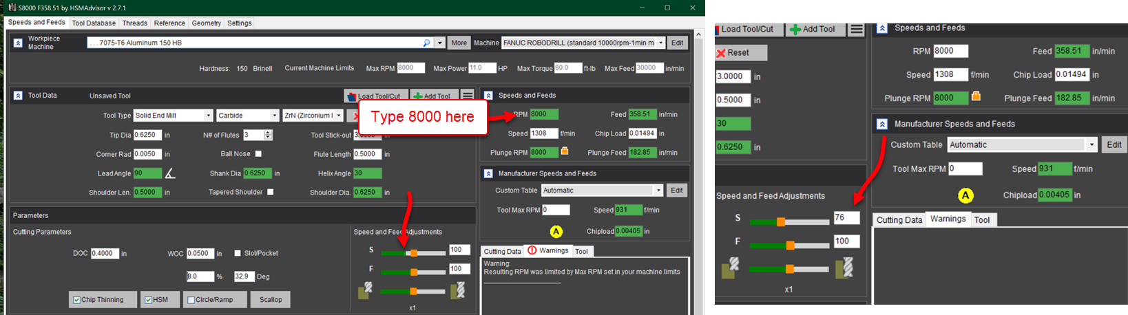
The big differences is that the Mastercam RCTF is taking a very limited view of the cross section of tool to engagement angle, and trying to keep that consistent. HSMAdvisor is looking at the tool stickout (Longer means more deflection of course), # of flutes (more flutes = thicker core = less deflection), coating (big difference in 4340 with TiN vs AlCrN!), angle of the helix (are more flutes in contact at that moment or less? That affects rigidity and material removal), etc., etc., If you have the machine set up right, it'll help keep you in the proper torque band, too. Maybe on your spindle if you drop below 2000 RPM, you lose torque, so 1800 RPM = 25 IPM, but 2200 RPM = 45. One thing I've found is 100% is "normal" high quality setup. If you're holding things securely in a regular ol' Curt vise with a quality single point/weldon tool holder on a normal Cat40/50 machine that's in good condition, it'll work great. If you're using an older machine where no one has adjusted the gibs in a while, your tool holders are clapped out and you're often using an ER collet, etc., you'll want to play down at the shallow end of the pool a bit more (75-80%). If you're using a more modern/well kept machine with a good control, shrinkfits, dovetail workholding, feel free to crank it up into the 120-130% range. In my garage, on my robodrill, for example, I generally end up in the 80% range for dynamic roughing. On a new Okuma that I'm helping out with right now, we're in the 120% range. Pay close attention to the Tool Deflection down in the bottom box. That'll really affect the life of your tool and surface quality. Oh, and another handy trick, if you enter a situation where the feedrate or spindle speed is reduced due to safety margins/machine limits, it'll slow down the feed/speed shown as the little green bar below the slider. If you're trying to figure out what % of a reduction that is, you can type in the number on the RPM or Feed line in the upper right, and it'll set it there so you can match the other:

-
Tool Manager - Sorting Column Options
Aaron Eberhard replied to SuperHoneyBadger's topic in Industrial Forum
The highlights for me are the cool surface manipulation tools in it to create extensions, plugs, trims, etc. There's also a really well done parting line creator. If you do electrodes, there's an electrode maker that will take your parts and create the electrode and all supporting plates/fixtures/etc. for it. If you're more into trimming molds, the 5 axis toolkit makes it really easy to manipulate vectors and smooth out the motion on the edges, as well as auto-selecting edges to make selecting & generating the paths way faster and easier. I've heard that the fixture plate/support structure designer works really well, but I haven't personally used it. It looks like a time saver if you're doing larger molds you have to hold for trimming/secondary operations. -
How much stock are you telling it to leave on your model on the Model Geometry page?
-
On a normal Fanuc a g98 is return to initial plane after drilling the hole. G99 is return to the R value. In your g98, you've only got one hole, and it has to return to the clearance position afterwards due to your settings, so it's going to choose to output the drill cycle that returns to your initial plane. In your g99, after starting at your clearance position, it's returning to a different height (R (retract) plane), so it'll have to output g99. That's my guess, anyway