Richard Thomas - Mastercam UK
-
Posts
967 -
Joined
-
Last visited
-
Days Won
2
Content Type
Profiles
Forums
Downloads
Store
eMastercam Wiki
Blogs
Gallery
Events
Everything posted by Richard Thomas - Mastercam UK
-
 Sorry that no-one had picked up on this issue before now : usually when I have a similar problem it is due to the geometry. The problem might be that the wireframe you derived from the Iges file isn't quite flat/horizontal. If the wireframe drops even a little bit in the X axis then that section would be considered an undercut and by default the roughing does not machine undercuts. Ideally you would then fix the geometry but you can also force undercuts in the Plunge Parameters page of the Lathe Rough toolpath. Hope this helps!
 -
importing text question
Richard Thomas - Mastercam UK replied to cherokeechief79's topic in Industrial Forum
You might have access to the Raster to Vector user app on your system (go to Run Add-In on the Home menu and find Rast2Vec.dll). If you can find a way of exporting from Word as a TIFF, BMP or JPG (Tiff preferred for best quality) then you should be able to import that into Mastercam. -
Mcam 2018 Fillet Chains / Chamfers question...
Richard Thomas - Mastercam UK replied to Dontech's topic in Industrial Forum
Yes a way to un-fillet would be nice. Many years ago you could use "0" as a radius in the fillet function but that went away after a redesign of that command to make it more fuctional in other areas. Best request that your reseller turn this into an Enhancement Reques with CNC. -
strange toolpath request
Richard Thomas - Mastercam UK replied to cherokeechief79's topic in Industrial Forum
Thanks Ron, most kind sir Master80, please start a new thread if you want to continue discussing your needs. -
strange toolpath request
Richard Thomas - Mastercam UK replied to cherokeechief79's topic in Industrial Forum
Ok sorry Master80 - you asked how to generate a path that looks like the video -
strange toolpath request
Richard Thomas - Mastercam UK replied to cherokeechief79's topic in Industrial Forum
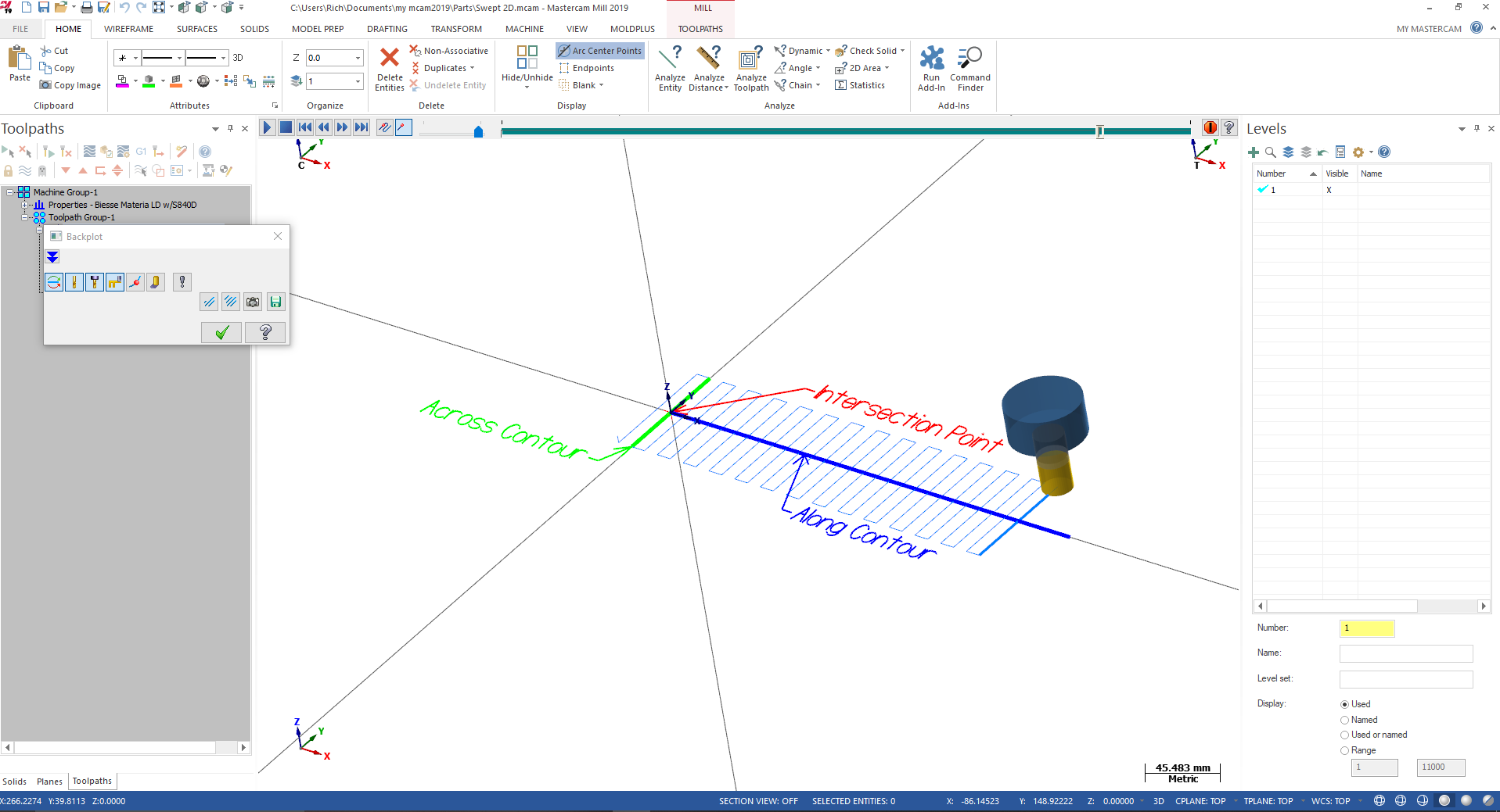
I would unroll the edge geometry and use 2D Contour with Axis Substitution enabled. This gets you the result similar to your video (see file attached) helix_cut_axis_subs.mcam P.S. If you want to discuss this file, it would be best to start your own main topic in the forum rather than continuing here please.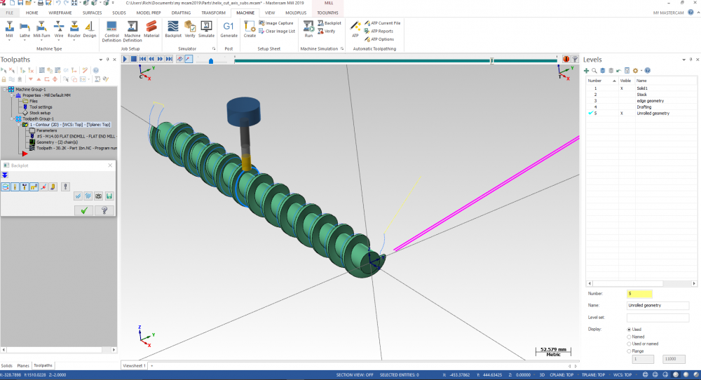
-
Circle 5 Axis Outputs Linear Moves
Richard Thomas - Mastercam UK replied to ad1187's topic in Industrial Forum
Circle 5-axis produces what is known internally as Type 11, or G11 moves. These are always linear; in fact they aren't just XYZ positions they are XYZUVW coordinates and are used in all the other multiaxis toolpaths too (as far as I know). Type 11 moves cannot be converted/filtered into arcs I'm afraid. If you really must have arcs then you'll have to create planes and use the 2D Circle Mill cycle. -
strange toolpath request
Richard Thomas - Mastercam UK replied to cherokeechief79's topic in Industrial Forum
The video is just a black screen for me Master80 -
strange toolpath request
Richard Thomas - Mastercam UK replied to cherokeechief79's topic in Industrial Forum
I used two lines but you should be able to tweak the line lengths into something useful (I guess you might have to convert it into English first lol) Swept 2D.mcam
-
Mastercam 2019 Bugs
Richard Thomas - Mastercam UK replied to Corey Hampshire's topic in Industrial Forum
Just to add that a number of Multiaxis toolpaths support Multi-threading too, such as Flow and Curve five-axis as well as several more sophisticated paths like Parallel and Morph. -
If you are doing a 5-axis toolpath then the backplot rotary axis option does not affect the g-code at all. It only affects the backplot function when the backplot feature called "simulate rotary axis" is enabled. If you doing a 4-axis toolpath, you'll see that the word "backplot" dissappears from the name of that command; in 4-axis mode this feature definately can affect the g-code output and may determine whether you have A, B or C axis calls in your 4-axis toolpath.
- 1 reply
-
- 1
-

-
IGES Files Opens in Metric
Richard Thomas - Mastercam UK replied to Dan Schnars's topic in Industrial Forum
Go to Files/Configuration and then right at the bottom of the page there is a section called Current. Click on the drop-down menu and switch that back to English. Accept the warning about switching units, press the green check to save the settings and you will see a question asking "Scale current part to English?". Say yes and it will switch your units and scale the file properly. -
changing multiple diameters
Richard Thomas - Mastercam UK replied to metalmansteve's topic in Industrial Forum
If the arcs are wireframe and you are using 2018 or 2019, first of all select all the arcs you want to change. Then use Analyze Entity, change the diameter of the last arc and press the blue "*" symbol next to it. That button is called "propogate arc radius" and will set the other arcs to the same size. -
I'm not very good with imperial values (ironic since I'm from the UK) but I'd suggest turning off the Filter. If you are getting flatspots/gouges I'd suspect the tool is travelling relatively long disatnces between tool positions, and that is what you'd typically get with the Filter active.
-
Well, that's odd, even for MC
Richard Thomas - Mastercam UK replied to Mark VIII's topic in Industrial Forum
If you right click on a solid in the Solids Manager you can now choose Analyze. Not an direct answer I'm afraid but at least it could tell you the level that Mcam *thought* the solid was on! -
Sorry Snoop; you are correct when you say what you want isn't available in Mcam. I presume that it could be added if enough people requested it. Bear in mind that Mastercam is primarily about machining and we're not an Autocad competitor.
-
Well, funny story about that! It used to be "R", but the developers decided to reassign R to the "reselect" function in the Circle Centrepoint command so they switched the radius command to something else. Then they needed consistancy among similar shortcuts. Having said that, "R" still works with the circular dimension the first occasion you try to use it but not subsequently... you haven't heard tha from me, right?
-
Go to the Drafting ribbon bar at the top of screen and find the "Circular" dimension command. Once you have clicked in a circle you can press "U" or "D" on the keyboard to switch between radius and diameter readouts. You can do this with Smart Dimension mode too but that requires a bit of practice/instruction to use properly.
-
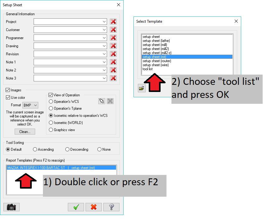
Try this out... go to run a setup sheet (Pre-select the ops you want to generate tool data from then right click in the Toolpath Manger, or choose Setup Sheet in the Machine ribbon bar). On the Setup Sheet options page you can change the reporting template that it uses to generate the data. Double click on the current template (see screenshot) and then choose the "Tool List" item. This will generate a file like the detailed report option mentioned above but only for your selected operations.
-
If you had the intention of using the Okuma and only required Mill 2D operations but not Multiaxis, you could use a custom shortcut to launch Mastercam - I think ' "C:\Program Files\Mcam2019\Mastercam.exe" /M2 /noX5 ' should do it. The other options to enable/disable products are in the Administrator Guide for 2019. I have the feeling though that you may have already been down this road
-
Edit Common Parameters
Richard Thomas - Mastercam UK replied to Mark VIII's topic in Industrial Forum
My guess would be that Edit Commons hasn't been updated yet to reflect the newer linking settings. Email your reseller or CNC and make and enhancement request. -
I'm happy to be able to help in some way Gracjan
-
Can you sort new swarf to cut by depth or slice ?
Richard Thomas - Mastercam UK replied to Leon82's topic in Industrial Forum
When you have both Depth Steps and Layers set up (i.e. both set to more than "1") then an option will appear in the Sorting section at the bottom of the page. Its called Sequence and will let you order the cuts by slice or by layer. EDIT - oh-oh... after re-reading your post I realised that you wantd to Swarf machine in a waterline style order (one depth pass on each surface before going down to the next depth). Turns out that it doesn't look possible to cut in that order with muliple surfaces. Sorry! -
I'm not quite sure exactly what you mean by "surface point" but: 1) this command will let you select a surface or a solid, and 2) if you have wireframe point already placed on a surface you can select it - you just have to select the surface first and then you can snap on the point. Hope this helps.
-
One thing that affects the appearance of surfaces when zoomed in is the Surface Shading "Chord Height". It is found in the system Configuration under Shading. The default in metric is 0.025mm but if I have a part whose edges are looking rough I reduce it temporarily to 0.01 or less. You may need to force a screen display regeneration afterwards (CTRL-Shift-R) to update the image.