Richard Thomas - Mastercam UK
-
Posts
967 -
Joined
-
Last visited
-
Days Won
2
Content Type
Profiles
Forums
Downloads
Store
eMastercam Wiki
Blogs
Gallery
Events
Everything posted by Richard Thomas - Mastercam UK
-
 I know I'm beating a dead horse now, but that isn't going to stop me :D In 2019 you can use Wireframe/Line/Normal and create a perpendicular line from a surface. The use Surface/Sold Spehere from the centre of the line.
 -
I'd just like to add that as far as I was aware the Smoothing option is not about generating arc moves or nice co-linear passes that could be filtered into arcs. There are often more small 3D moves with Smoothing activated then without... the feature is designed to improve the appearance of 3D finished surfaces by reducing the appearance of moire patterns - it usually does this by creating more randomised, smaller moves in the program. It doesn't really straighten out wavy toolpaths.
-
For the first issue check the Autocursor settings for the mouse - you have a set of snapping options there and it may be that you accidentally disabled the "Origin" option. For the second issue... umm pass sorry! Off the top of my head I'm not sure why the Drafting option would stop allowing you to select full lines. Unless... your edges are actually solid edges (and not wireframe at all) in which case there is a "solid edge" toggle switch in the Autocursor ribbon bar too
-
ModuleWorks Help File - 08.2017
Richard Thomas - Mastercam UK replied to a topic in Industrial Forum
Thanks - the most recent one I had dates from 2013 and is "only" 278Mb -
FWIW, the toolpath you selected in X9 - Surface Finish Project - still works the same way in 2018 (because it's a "legacy" toolpath and the interface hasn't changed) so you will still have the "show" buttons for drive and check surfaces. If you haven't found that toolpath yet in 2018, you need to right click in the Toolpath Manager, go to Mill Toolpaths, and you will find all of the old strategies
-
I'm under the impression that curves created during import are created by the solid modelling importer. It's not a case of Mastercam quietly running Create Curves after the solid model is imported. I just wish I had some written confirmation of that for you; I was told about this a long time ago - like back in the X4 days when I was trying to trace a bug in Create Curves with CNC.
-
Very frustrated X6 user, lost ribbon bar and...
Richard Thomas - Mastercam UK replied to Dontech's topic in Industrial Forum
Try starting Create/Line/Endpoints (or draw an arc or rectangle....) Unless there is a bigger issue, the Ribbon Bar should come back floating somewhere on your screen and you should be able to drag it back into it's proper place. -
There used to be a function called strtpgroupname which would get the name of the Toolpath Group out into the NC program. (actually... now that I think of it I'm not sure what would have happened if you had multiple toolpath groups!) This function does not appear to work anymore - I updated an old X3 post and the customised toolpath group name (e.g. "Counter top") just comes out as "Toolpath Group-1". Is there still a way of doing this?
-
Hi Roboter, Well that is good news :-) I hope your reseller can come through with some training materials.
-
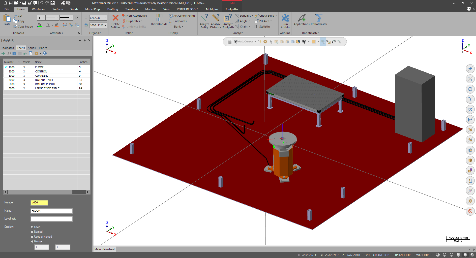
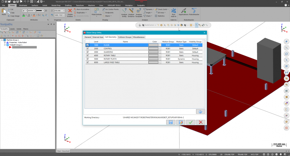
Hi Roboter, I've been looking through my work laptop and I'm sorry to say that I can't find a tutorial or even video to walk you through the Robot Setup Utility :-( I'm next in the office on Monday - I'll have a look there too. In the meantime I can share a screenshot of a old cell from a University that I helped set up. You can see that the main Mastercam 0,0 origin (you can see this by pressing F9 function key on you keyboard while using Mastercam) represents the origin/datum of the robot - your cell needs to be drawn around this point. You do not need the actual model of the robot in the .MCAM part-file when you run the setup utility. Also, you can see that in the Levels Manager, each main component is on a named level. In the screenshot of the setup utility you can see there are two visibility options: Default and Housing. The Housing option allows you to later make those sections transparent/invisible later. I wish I had more time to talk about the other important topics such as the External Axes and the Collision Groups sections. But once I start it'll be quite a long topic to write down and I haven't got the time at the moment I'm afraid. Speak to your reseller and see if they can get a tutorial from Robotmaster for you. Hope this helps fill in some of the blanks and sorry I couldn't be of more help.

-
Hi Roboter, Please accept my apologies for not replying sooner - it's been a busy time the last week or so. As far as I know the Robot Setup Utility is included at no extra cost with Robotmaster. I'm afraid my laptop is at home today so either this evening or tomorrow I shall try and find some documentation or video instructions for the utility. To reply to your query regarding levels; you have the potential to make different parts of the robot cell either visible or invisible when it comes to viewing the toolpath simulation. To do this you can - for example - place the floor geometry on Level 1, the walls on Level 2, the table on Level 3 etc, before you run the Robot setup utility. I can't offer any more details right now as I'm actually using a customers' PC to write this message
-
Have you got the "Robot Setup Utility" installed for Robotmaster 6.4? If you haven't you have to get hold of the "Robotmaster_V6.4_ToolKitActivator" download. You should be able to download it from the Robotmaster website (login required) or through your reseller. Before running the utility you have to have the robot cell drawn up in Mastercam. The cell is constructed relative to the robot origin, i.e. the robot origin should be at X0Y0Z0 and the rest of the cell drawn around that point. All the main features of the cell (walls, floor, table, cabinets) should be named on different levels. There are more steps involved but I'm afraid I haven't the time right now to go through it all. I'll try to follow up later today.
-
You can do this sort of thing with the traditional 2D Pocket toolpath - set the roughing strategy to Morph. Also ensure that your two chain starting points are in the same relative position, i.e. if the circles' chain starts at three o'clock, break the rectangle so that its start point is in line with the circle.
-
For the first issue, check the properties for the Icon/Shortcut used to start Mastercam - perhaps someone has tried to launch Mastercam with an unlicenced product level, i.e. the file path reads "C:\PROGRAM FILES\MCAMX9\MASTERCAM.EXE /M3". Try deleting any text after ".EXE" For the second issue, you mention he starts a measurement device. Is there any chance the guy is still using a white parallel port dongle has and has the measurement device plugged in on the end of that? I could be way off base here, because, but I have a feeling there were still some old white dongles in circulation that could run X9.
-
I was never confused!! p.s. sorry for post-editing the - errm - post
-
I just discovered - not by accident at all - that in 2017 and 2018 you can use single alphanumeric keys to launch commands without the need to press ALT, CTRL or SHIFT. You can launch Wireframe Line Endpoints with the letter L for example. But you might run into conflicts with certain combos.... for instance using E to launch Line Endpoints and then trying to use E again to use the Endpoint auto-cursor override doesn't work (although you could still use the auto-cursor drop-down menu).
-
Local Nethasp not recognized
Richard Thomas - Mastercam UK replied to SlaveCam's topic in Industrial Forum
From Mastercam 2017 the NetHasp has to be run in Network mode now to launch Mastercam, even if plugged in locally. (In addition the Network Licence Manager has to be running as a service, as is usually the case.) The only time you should use "Local" now is when updating the NetHasp licence. -
(Also posted to Mastercam.com forum) Both my colleague and I had problems today with Mcam 2017 suddenly not starting properly. The splash screen would appear, the 2017 interface would come up but then the software would hang at that point (Task Manager job to close it). I suspected a Windows Update might be at fault and sure enough there has been an update to the Nvidia driver - "12/29/2016 12:00:00 AM - 21.21.13.7654". We both rolled back to the previous installed Nvidia driver and 2017 started booting up properly again. Windows 10 Home 64 Bit by the way. p.s. although the date on the driver is December, Windows installed it today.
-
I think what you might be looking for is in the Utility page of the Parallel to Surface toolpath (and other "advanced" multiaxis toolpaths). There is an option called Axial Shift that can allow you to drop the tool down further than the default calculation (not knowing what your part looks like though, Your Mileage May Vary )
-
You can try using the Verify mode that is built into Machine Simulation (you might have to switch on the "Mastercam Simulation" toolbar to see the "Run simulation verify" button). From that utility you are able to set a static view down the tool axis. Seems to align the machine X-axis vertically as opposed to along the normal left-to-right direction, in my limited testing. You can always spin the model around on screen though.
-
If I want to turn incomplete arcs into full circles I do it via Analyze Entity Properties (instead of Edit Close Arcs) and set the angle to 0 - 360 degrees. That way I am less likely to be surprised by circle toolpaths starting in funny places. EDIT - ahh, Ron beat me to it on this one; his idea was to help with mutiaxis toolpaths but basically it's the same deal here. I'll throw in an oldie though. You normally cannot select the end/corner of a surface entity (perhaps you are trying to use Create Line Endpoints) but if you press the Endpoint cursor override you'll find that surfaces will highlight - you'll be able to click close to the surface edge and *usually* the snap will jump to that corner.
-
Start with rrichard's idea to backplot the toolpath and then save the geometry to a level. Look at your shape in the Isometric view to see that you have also got vertical wireframe that you will probably want to delete. Then what you can do is use Xform Offset Contour on the new toolpath geometry and offset it by the radius of your cutter. Make sure that the "corners" option is set to either Sharp or All. I think that will give you what you want.
-
Need help matchin text to arc
Richard Thomas - Mastercam UK replied to randommachinist's topic in Industrial Forum
How about creating a draft surface from your arc underneath the text and then projecting the wireframe down to the surface (or just using the original text with the Surface Finish Project toolpath) EDIT: Henk beat me there by a few seconds -
Thanks a lot Mick - again!
-
Changing Surfaces/Solids down to Wireframe issue
Richard Thomas - Mastercam UK replied to bgott's topic in Industrial Forum
To manipulate solid features in Mastercam X4 you would need the additional Solids licence (because even if you converted some features into surfaces you would not be able to convert them back to a Solid afterwards in Mastercam X4 unless you have the additional licence.) The best solution would be to convince your employer to update to Mastercam X9 because this includes Solids now without an additional licence fee.