PAnderson
-
Posts
199 -
Joined
-
Last visited
-
Days Won
4
Content Type
Profiles
Forums
Downloads
Store
eMastercam Wiki
Blogs
Gallery
Events
Everything posted by PAnderson
-
Just had this yesterday. Parameter #5148 on newer Fanuc controls. Set the Z box to 1 for a positive X shift. Set to -1 for a negative X shift. You set it in the Z box because you are boring in Z Axis. If you look, it is probably set to 2 or -2. if this is an older control, try #5101.
-
I don't understand why you would need to mirror a plane unless for visual reference only. Technically, planes stretch to infinity. The only thing important is the height from the WCS and the normal vector. Paul
-
OK, solved. It was answered over on the Mastercam forums. It seems that switching from shaded to wireframe and back again solved this little problem. For future reference.
-
Thanks but that was the first thing I checked. Any other settings in the NVIDIA panel to check?
-
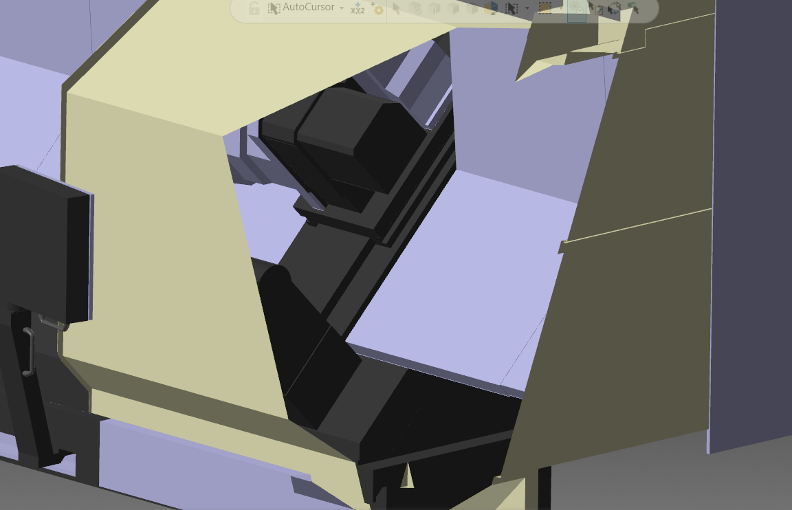
Mastercam 2022 only. I am getting this strange clipping on my parts now. It seems to be only when the "TOP" plane is selected. Also, it seems to be the worst when the Z axis of the genome is facing towards or away from the screen. Same file does not do this in 2021 and I get the same result with other solid files. The image I uploaded is as the part swing during rotatio and it gets worse as the becomes more end on toward the screen. Any ideas? I even took the STEP file and converted it to Parasolid and got the same thing. Seems to be the graphics card but I have had the same setup since MX2017. Settings in my NVIDIA setup? MX2022 is a newer setup, less than 6 months. Been happening since installation. Driving me crazy now. Paul

-

Doosan DVF 8000 Verify/Post issue?
PAnderson replied to Bill Henderson's topic in Post Processor Development Forum
If indeed this was programmed from the center of rotation, then the 19700-19705 parameters would not play a role at all. In TCP they certainly would. These values would be in the post processor. #19702 and #19705 would need to be exact. With TCP, #19705 is not used. It would be used when programming from the COR and MUST be exact. The kinematics parameters would indeed affect G68.2 if that is all that was used. Could you post more of the code? I have all of my posts to use G68.2 to position the tool safely over the part after A and C rotation, turn it off and straight to G43.4. Almost always, I suggest NOT updating the kinematics right after install because the values from the factory are the best during machine build. I ask customers to run the machine with their first parts until errors are seen, then take a look at what is going on. Was the machine lasered during installation? Is it bolted to the floor? I'm in 5 axis applications with Doosan. Call me if you have questions. 973-618-2457 I may have already been involved with this machine through Adams. Here are the values from a recent machine, newly installed. N19700Q1L1P0.0L2P0.0 N19701Q1L1P-0.012L2P0.0 N19702Q1L1P-739.932L2P0.0 N19703Q1L1P0.0L2P0.0 N19704Q1L1P0.012L2P0.0 N19705Q1L1P-100.068L2P0.0 -
And as soon as you update, Win11 will be here. Brace yourselves.
-
Renishaw omp600 not turning on
PAnderson replied to Leon82's topic in Machining, Tools, Cutting & Probing
How are you turning it on? Renishaw probes should be able to use an M code or to turn on with what Renishaw calls spin on, as in a centrifugal switch. It could have been changed somehow, usually by holding the stylus down during battery insertion. Doesn't take much to change probe settings. I would download the Trigger Logic app from Renishaw and use it to partner a probe or tool setter and to check/change settings. -
I must have had the old/wrong swarf toolpath.
-
In your Swarf toolpath, go to the "Collision Control" setting page. Set to Lower Rail and in the Distance Above Lower Rail setting, use a negative number of your choosing. Paul
-
problem with Doosan mill turn LYNX 2100LY
PAnderson replied to Patrick Marthy's topic in Machining, Tools, Cutting & Probing
Can you just home the Y axis before using that tool? -
Yeah, that's what they got. We sent them a doc for the parameters to set. Let's see what happens. Thanks for the sample code. Paul
-
So, what are you saying Ron? Use TWP instead of TCP? That was my thinking. TCP should work but isn't that overkill for an HMC? Thanks Ron.
-
OK gentlemen, this is a new one on me. And I will preface this by saying just because I have not seen this before doesn't mean it hasn't been done. We have a customer that purchased TCP(G43.4) on their horizontal machining center. So I am asking the 5 axis (4?) pros here if they have encountered this? Possible? Advisable? Better options? I don't want to touch this one since I have absolutely no experience with this use of TCP. But since it's been thrown in my lap, I guess I will have to pursue this. Can anyone comment on this? I would have had no problem suggesting TWP for this application. Paul
-
Rotary broach source
PAnderson replied to So not a Guru's topic in Machining, Tools, Cutting & Probing
These were my goto guys when I was needing rotary broaches. https://www.genswiss.com/broach.htm -
Nothing wrong with that either. You would only have to live with the output you had though. It would still work, just in a different way. Paul
-
I changed your swarf to 3 axis in tool axis control and created a new plane for each swarf toolpath you have. This drives a table rotation and depending on the output, G43.4 or G68.2 will give you a basically, 3 axis toolpath with A and C locked. A lot depends on your post. Me? I would have just used a CONTOUR toolpath with the same two planes driving the tilt. This should output G68.2, which for 3 axis toolpaths is prefferable. Paul 61345-160R1 rEV-2.mcam Ahhhh, you beat me to it.
-
rotator location on 4+1 fanuc series 31i - modal b5
PAnderson replied to Seedy steve's topic in Industrial Forum
Sorry to hear about the issues. EOP is the Easy Operator panel and can be found by pressing the CUSTOM 1 key under the screen. How old is this machine? I am surprised it was out that much. Did you call your dealer or us and report this? We need to know these things. Paul -
rotator location on 4+1 fanuc series 31i - modal b5
PAnderson replied to Seedy steve's topic in Industrial Forum
Additionally, the VCF850 with Fanuc 31i-B5 is not only a 4+1 machine. It is also capable of full 5 axis machining. -
rotator location on 4+1 fanuc series 31i - modal b5
PAnderson replied to Seedy steve's topic in Industrial Forum
I work for Dosan. If the above is true about the machine going out after moving the machine, then correcting the 19700-19705 parameters will not work like you think. The machine MUST be mechanically re-alligned before resetting these parameters. There is also a good chance that those parameters need not be changed if the mechanical soundness of the machine is restored. The VCF850 also has an app for checking these parameters. It's called DCPi and you will find it in the EOP screen. DCPi can be run and if errors are found, it's a good idea to check the machine mechanically. All axis MUST be alligned to one another or the COR cannot be found accurately. Paul -
Colin is correct in his description. This isn't just something that happens on Fadals. Fanucs exhibit this behavior also. I had this happen twice on very expensive mold cores. And more recently, a customer was blaming the machine. While it was the machine in a way, the real culprit was the fact that tiny arcs were being created. If the end point is so close to the start point that the control understands it as a complete arc. In the case of our customer, the arc length was only .0002" with a radius of over 100". Somewhere in the CAM system, there needs to be a minimum arc LENGTH setting. Something the control does NOT see as ambiguous.
-
Head/head is where both rotaries are on the spindle head. Head/table is where one rotary is on the spindle head and the other is on the table. Also called a hybrid. Table/table is where both rotaries are on the table. Most common.
-
How does Mazak get away not having G68.2 on a 5 axis machine?
-
If this is truly an indexing situation, using G68.2 would be most desirable. That would also allow the use of standard cutter comp, G41/G42.
-
Don't know 'cause I'm not a new kid. But I am an old fart.