The Cathedral
-
Posts
736 -
Joined
-
Last visited
Content Type
Profiles
Forums
Downloads
Store
eMastercam Wiki
Blogs
Gallery
Events
Everything posted by The Cathedral
-
It was a question, not an assumption; and the pedantry is entirely irrelevant because you know and I know that in our field, the jargon we use doesn't follow the Mariam-Webster definition. Could I call them machinists? Yes. Would I call them machinists? No.
-
You would consider someone who can't read vernier style mikes and calipers skilled?
-

Pitch in your little gems that make mcam life easier
The Cathedral replied to jlw™'s topic in Industrial Forum
Works as it should for me. TD=010060 M323 N60 (BORING BAR 3/4" SHANK) M01 G00 Z.1354 M08 M175 G97 S251 M03 G95 X6.8477 G96 S450 G01 G41 X6.8477 Z.0354 F.007 X6.757 Z-.01 Z-.172 X3.52 (YO) X3.5 Z-.182 Z-.73 X3.06 (WHAT UP DOG) X3.04 Z-.74 Z-.835 Z-1.15 Z-1.54 X2.94 G40 X2.94 Z-1.44 G00 Z.1 M09 M174 M05 G97 S200 X60. G20 HP=4 M01 -
Sounds to me like you're doing a sort of custom thread, in which case you'll probably not be able to use a standard tool. Unless you either a ) counterbore the thread to below the surface or b ) grind relief on the threadmill, once you get past the LOC on the mill you'll be rubbing the shank and wiping out your threads.
-
Pitch in your little gems that make mcam life easier
The Cathedral replied to jlw™'s topic in Industrial Forum
Yeah, but have you tried using the "invert selection" function yet? -
Make sure you analyze the flow of a job, from from the time it's approved to the time you tear down the machine. I don't program for all the machines we have, but my boss puts all the travellers for upcoming jobs into my inbox. This way I can analyze the jobs and determine what machine it would run best on, and if I can improve the process by moving it to a different machine. Most jobs then get filtered directly to the floor as they're look-up jobs and need no extra intervention. The others I program and order special tooling for. It's also important to keep in contact with the guys you program for, so you know if they run into trouble or the machine goes down and you need to move it to a different cell.
-
Pitch in your little gems that make mcam life easier
The Cathedral replied to jlw™'s topic in Industrial Forum
You can do that. Select the "create line" tool. When it asks you for your first point, type in what you want, say X1Y1. Then hit enter and voila, your first point is at X1 Y1. Then hit A and type in your desired angle. Then hit L and type in your length. If you're in lathe D+ Z+, use D instead of X. -
Pitch in your little gems that make mcam life easier
The Cathedral replied to jlw™'s topic in Industrial Forum
This. You can also alter dimension notes and labels the same way. If you need to change what the label says, move it, resize it, etc after you already made it, just select the label and hit F4, and use the "Edit Text" option to change the text, and the "Quick Edit" option to move it and access the size option toolbars. -
If you have anymore stupid question like this one, keep 'em coming! I think quite a few of us learned something new.
-
We run parts on a horizontal where we have to insert bronze bushing. I have the toolpath programmed using point toolpaths, but I set the approach and retract points at a position near the door, so the operator can open it up, slip on a bushing, and then the machine inserts it.
-
X7 is as far back as this computer goes, but in there you can do it easy. In the operations manager box, click the little triangle in the upper right corner, then select font.
-
So, basically it breaks down like this: WCS is your coordinates and work offset Tool plane is your "direction" of the tool, or the plane that perp to the tool Comp is an arbitrary plane that can skew your toolpath Does that seem right?
-
The reference points are points you use to start and end your toolpath. For example, if you have a really long tool that you need to move away from a fixture before you toolchange, you would put that point in the "retract" dialog box. The home position, I have never used. I suppose how your machine and post operates would dictate how you would use it, but on our Doosans and Okumas we never use it.
-
Barrell Mill Supplier
The Cathedral replied to The Cathedral's topic in Machining, Tools, Cutting & Probing
Mastercam does support it, but it only works using the multiaxis toolpaths. "Regular" toolpaths don't recognize it and treat it as a bullnose. -
You have fingers and can type on a keyboard?
- 182 replies
-
- 2
-

-
- custom macro b
- cnc
- (and 2 more)
-
Barrell Mill Supplier
The Cathedral replied to The Cathedral's topic in Machining, Tools, Cutting & Probing
I think I'm going to give one a try. I'm actually going to use in on a 3-axis horizontal. It's doing a tapered bore, and nothing I couldn't just use a regular ballnose for, except I'm looking at cycle time. If I could cut the cycle time by 50-60% by doubling or tripling the DOC and still get an acceptable finish, I think it would be worth it. Plus the quotes I've got so far haven't been too extreme to scare me away. I'll let everyone know if/when it works out. -
Barrell Mill Supplier
The Cathedral replied to The Cathedral's topic in Machining, Tools, Cutting & Probing
I didn't see one in their catalog. The picture is deceiving--it's not an straight-angled side, it's actually a radius. -
Does anyone have a good source for buying barrel mills for 3D profiling? Like the ones offered by Emuge. I figured they must be prolific enough now that Mastercam offers a geometry option for them when you create a new tool. However, I can't seem to find anything but burrs, and I need an actual endmill. Any thoughts?
-
Horizontal Programming your method?
The Cathedral replied to crazy^millman's topic in Industrial Forum
This. Back is Y is C0. Y moves in the Z, rotate in the right plane for the front, Top is nothing actually but you *must* use it. -
Primary Datum on a Curved Surface? GD&T
The Cathedral replied to ahaslam's topic in Industrial Forum
The major caveat of that new spec is that it must be a mathematically defined surface, ie geometric, not organic. If it's someone's flowing pipe dream of a mold, it does not fall within those specifications and therefore cannot be used. -
We do extensive milling on our Okuma M-Y equipped lathes. It works, and it works well, but your end tooling will be the biggest drawback. If you're not on a machine with a dedicated milling spindle, you'll be sending your live tooling back for repair more often than you'd like. Ours are cooled by the coolant, so you can't run it dry for too long. Plus, cooling/lubricating with a water-based coolant has it's own obvious problems. If you're talking about short- to medium-run parts with a little bit of regularity, you'll be fine with these kinds of machines. If you're talking about production runs or frequent runs, you'll want to look at a dedicated mill-turn.
-
If they program by hand, chances are they aren't doing parts as complex as what you and I see. There is no easy way to dimension the toolpaths inside Mastercam. One way you can do it is to backplot your toolpath inside Mastercam, then save that toolpath as geometry. Then you would have to plot out each dimension using the dimension tools. Or you could, you know, use the Mastercam program to write the program like it's supposed to do...
-
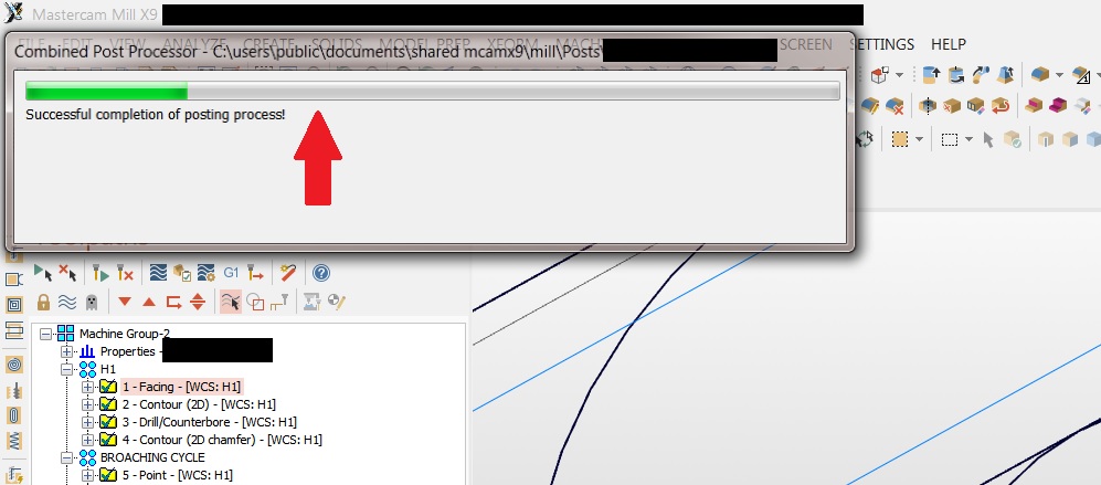
You say it freezes when it posts. Does it freeze while the green progress bar occurs, or before?

-
MCam Mill/Turn... something doesn't add up for me
The Cathedral replied to jlw™'s topic in Industrial Forum
I guess I'm confused on what your asking. If you're asking if the way I do it is the way it's supposed to be done, well, I'd like to agree with you... -
MCam Mill/Turn... something doesn't add up for me
The Cathedral replied to jlw™'s topic in Industrial Forum
Part orientation and WCS in lathe is nothing like mill. Looking at your first picture, you have your part oriented the wrong way. It's dumb, but when you draw a part in lathe, it's as if you're looking into the machine, instead of like mill where you're looking down the spindle. See the picture below. You should have your part oriented so actual lathe z = mastercam x, actual lathe x = mastercam y. In order to look "top down" on the part like you do in mill, you would have to use the "right wcs" view. C0 is the mastercam y axis. I never use anything other than the default "top" wcs when I'm starting a job; using the lathe z = world z and other things is just too confusing and never seems to work right for me.