The Cathedral
-
Posts
736 -
Joined
-
Last visited
Content Type
Profiles
Forums
Downloads
Store
eMastercam Wiki
Blogs
Gallery
Events
Everything posted by The Cathedral
-

Post processing for multiple machines
The Cathedral replied to themachinist's topic in Industrial Forum
It's not always that simple, though. For example, all our lathes are from the same maker (Okuma). However, after buying and upgrading machines for thirty plus years, you tend to end up with a whole mess of different controls. We have absolutely shiny brand new Okuma P300 controls, and we still have two perfectly running green Okumas with the green screen OSP5020, and damn near every version inbetween. It makes it a headache. -
Tool management software reccomendations.
The Cathedral replied to specv's topic in Industrial Forum
I tried searching and couldn't find it. I found your posts when you were just starting to investigate Cribmaster, but nothing beyond that. How much work did you have to do yourself to make it work the way you wanted? -
Tool management software reccomendations.
The Cathedral replied to specv's topic in Industrial Forum
Bump, if anyone can answer the last two questions -
Serialization macro
The Cathedral replied to MIL-TFP-41's topic in Machining, Tools, Cutting & Probing
A simple way to do it would be to add an incremental coordinate shift at the end of the digit macro. Have the main macro that calls up and evaluates the number to etched; etch the numbers through sub-macro, have sub-macro keep track of how much shift is applied, cancel all shift at the end of the main macro. You'd have to evaluate each digit to find out how much shift each on needs to keep an aesthetically pleasing distance. So, something like this: M98 P5000 (CALL ETCH PROGRAM) :5000 (ETCH PROGRAM) [logic to determine what number to call] M98 P0001 (ETCH NUMBER ONE) :0001 [etch number one] G50 W-.05 #500=#500+.05 M99 (and so on) G50 W#500 (CANCEL ALL SHIFT AND RETURN TO MAIN PROGRAM) M99 -
Checking a tight tolerance chamfer
The Cathedral replied to Rstewart's topic in Machining, Tools, Cutting & Probing
Is it 15 from the bore, or the face? 25/32 if it's from the bore -
Checking a tight tolerance chamfer
The Cathedral replied to Rstewart's topic in Machining, Tools, Cutting & Probing
Yeah, look up "trigonometry" -
What kind of machine is it? What control?
-
Checking a tight tolerance chamfer
The Cathedral replied to Rstewart's topic in Machining, Tools, Cutting & Probing
Ball bearing would only be good to check size after you've verified it's cutting to the right angle. Old school method? Machine a blank and saw it in half. Measure. -
I'd be more concerned about the fact that your R values are incorrect. You need a 4 place output, yours only have three and thus the numbers don't add up. (3.268*2)+.75 = 7.286 It doesn't account for the huge difference in diameters, but it explains why he wants even numbers: to eliminate that extra .0005 Your post is truncating it, and that probably leads to compounding errors.
-
Mastercam is laughing at me. (Cutter comp)
The Cathedral replied to barnaby thomas's topic in Industrial Forum
There is a "spring pass" option in helix bore, if you choose "circle" as the finish pass style. -
From the MODEL PREP dropdown, select Clear All Solid Face and Feature Colors
-
Mastercam is laughing at me. (Cutter comp)
The Cathedral replied to barnaby thomas's topic in Industrial Forum
Computer - all cutter comp is calculated and applied inside Mastercam. Changes to tool diameter must be made in Mastercam, and then re-posted. Control - NO cutter comp is calculated in Mastercam. G41/42/40 is output; operator is responsible for setting up machine to reflect actual tool diameter. Wear - Cutter comp is calculated and applied inside Mastercam using the defined tool diameter. G41/42/40 is output; operator only has to adjust the tool value in the machine control to compensate for tool wear. Off - NO cutter comp is applied in Mastercam; NO G41/42/40 is output. Tool cuts on centerline only. I use Helix bore exclusively; it has better options for roughing and finishing inside the toolpath; also, it's much easier to pick out of the toolpath manager. -
I really love the maintenance clause of these things. "Pay 10% just in case we do things." At least Mastercam puts out new stuff every year, be it good or bad.
-
Machine insurance?
The Cathedral replied to Matthew Hajicek - Singularity's topic in Machining, Tools, Cutting & Probing
I usually call Flo. -
Hard to tell, but judging by the old school design there is two jam nuts inside the thimble riding on the plunger; you'd have to adjust the jam nuts to move the plunger. Not hard, just trial and error.
-
We've used Jobboss for years; I personally have not had much hands-on with it until the last year. I have to say, it may be good for what it does, but it's UI is terrible. The thing that pisses me off the most is, in the job entry field, you CANNOT use enter to change a field. You have to use TAB. Who enters a number, and then hits TAB to confirm? But if you hit ENTER, it nullifies everything. We're switching to E2 after the first of the year.
-
3D SURFACING.....NEED A LITTLE HELP
The Cathedral replied to Art Siler jr's topic in Industrial Forum
LIKE FINGERTIPS ON THE SURFACE OF MY MIND -
G97 is a constant, unchanging RPM. You can use G97 and have the RPM stay the same, no matter what the cutting diameter. Think of facing: if you use G97 S1500, the rpm will be 1500 as it starts the cut at the OD, will be 1500 as it moves down, and will be 1500 as it moves to X0. No matter what, it's 1500. When you use G96, it changes. It will be slow at the OD, and as it moves closer to X0, it will speed up until it hits the max spindle speed. G50 sets the max speed, and that's important because, as the cutting tool gets closer to X0, it theoretically has to spin up to a bajillion RPMS in order to keep the constant surface speed you program. So G50 keeps the machine from spinning too fast for safe cutting conditions. However, when you program to use G96 in Mastercam, you will see an initial G97 move at the toolchange. This is put there because if you were to start in G96 mode, while your turret is in home position, the spindle would have to start spinning at 1 RPM or so. Having your spindle constant ramp up to max then down to 1, then up and down again isn't really the best practice. So it kicks out a steady RPM at the beginning. This RPM is calculated using the formula listed above, using your cutting start point as the diameter. That's why it's such a random number (like 1137 RPM). Once it gets into position and G96 kicks on, you shouldn't see any spindle speed fluctuation and it will go right into the cut at the appropriate speed. G96 and G97 are mutually exclusive: you can only use one or the other, never both at the same time.
-
There have been a lot of these ridiculous spambot posts lately. I got a big chuckle out of the conveyor one that got necro-bumped yesterday.
-
I've never had luck doing that. For some reason it will work when I define it, but if I go back to it later it will lose its definition and freak out. I have to put a .005 rad to get it to stick.
-
I made a video a while ago to explain CSS. I use it when I teach a class on the basic principles of machining. It's meant to be played in the background as I stop and verbally explain the concept, but there is enough wording to give someone a good idea. Check it out if you want.
-
auto cursor tool ribbon.. where are you?
The Cathedral replied to CEMENTHEAD's topic in Industrial Forum
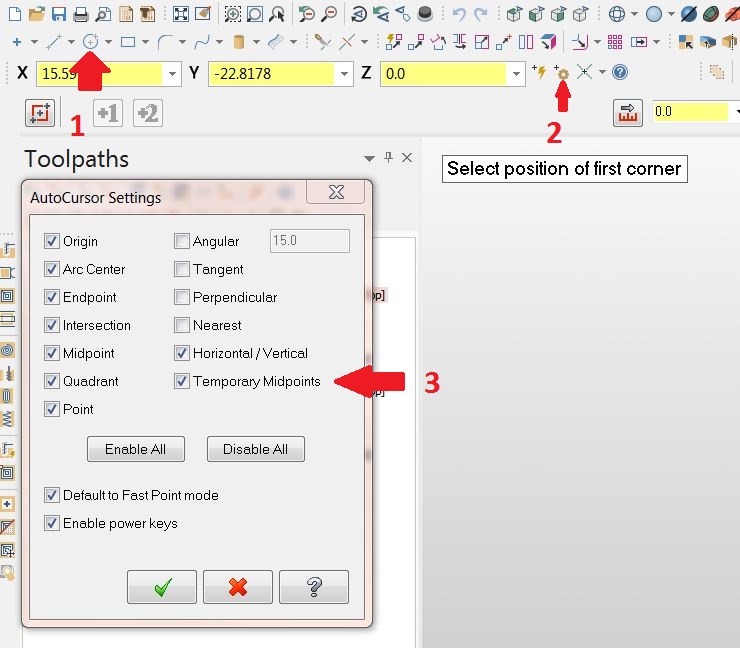
As long as you're on X9, it should be on autmatically. The feature didn't exist before X9. If it isn't on for some reason, do this: Click on a create geometry function, like circle or line. You don't have to actually create anything, you just need to get the autocursor ribbon active Click on the little gear symbol next to the autocursor ribbon Make sure the "temporary midpoints" box is checked in the options
-
After doing what these guys said, head over to mastercam.com forums and make a post letting them know the facemill definition is illogical.
-
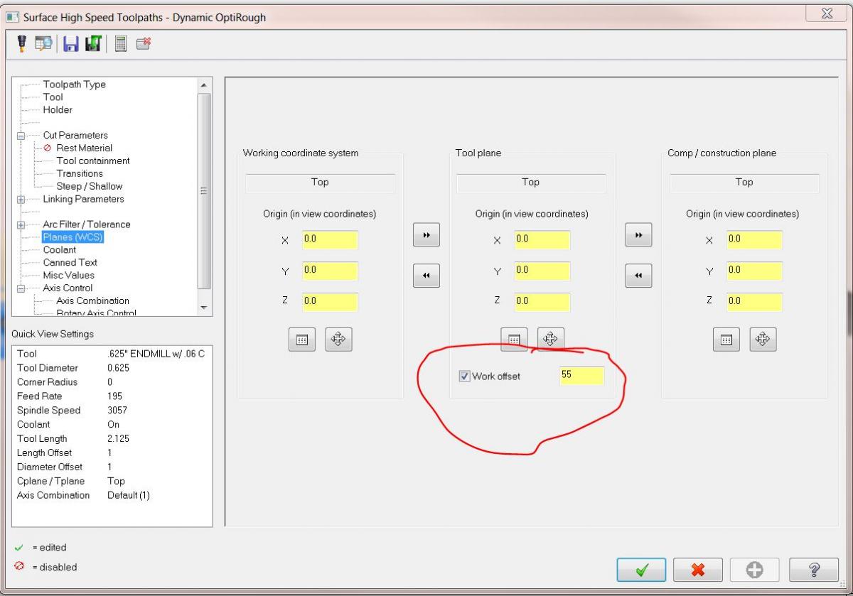
Make sure your planes parameters in the toolpath has this little box checked: I modified my post so I put in the actual offset number. Using "1" just doesn't work for me. If that box is checked, look in your misc. values. Depending on your post, there might be a variable in there that dictates your offset output.
-
doosan tool changer help
The Cathedral replied to Chris Rollins's topic in Machining, Tools, Cutting & Probing
What are you, australian?