


AMCNitro
-
Posts
677 -
Joined
-
Last visited
-
Days Won
3
Content Type
Profiles
Forums
Downloads
Store
eMastercam Wiki
Blogs
Gallery
Events
Everything posted by AMCNitro
-
Renishaw Prode diameter on Haas machine
AMCNitro replied to AMCNitro's topic in Machining, Tools, Cutting & Probing
That is exaclty what I was looking for, thanks Colin! Now, to the next question. Is it possible to measure features like the one the screen capture? For the 10 years that I've used a probe Iv only used it with VPS interface. Dont mind my desktop. -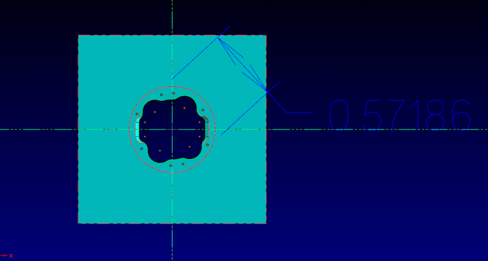
-
Is there a setting on the on the Haas machine to change the spindle probe diameter? I need to use the probe to inspect some features on a part, the standard 6mm probe is too big. Im trying to use a 3mm probe, I can calibrate it, but I dont see where the diameter call out is.
-
Did not know that about beryllium copper... Used to use a lot for electrodes, now I just tellurium copper for that.
-
What did you you define it as?
-
The holes would help, but then how much time are you wasting on drilling, to then just use the same toolpath as if you didn't drill? I would do like Rekd said, contour ramp and call it a day. Im curious as to which copper it is. 110 copper is PITA to cut, I hate it. 145 (telleriium copper) cuts really nice.
-
For one or 2 parts you can get away with 4F, but if you have a lot of parts and you want to go fast you need 2F or 3F. Its worse than aluminum as far as the chips welding to the tool. Also depends on which copper your machining.
-
Was about to say that
-
Faceting with Surface Finish Flowline Toolpath - How to Eliminate?
AMCNitro replied to Bill H's topic in Industrial Forum
On flowline, turn on the filter. I set it at 50%/50%. Zigzag works best, you get better arcs and cleaner tool motion. -
For that, on 5 axis mill, Id use a facemill. I'm the biggest proponent of any dynamic toolpath, but sometimes simplicity wins over. KISS method.
-
Operation Stuck In Multi Threading Manager Can't Delete
AMCNitro replied to dlewis1000's topic in Industrial Forum
JParis beat me to it. I sometimes have that problem too. I CTRL+ALT+DEL, plus Ill also restart the computer. Usually the operation will regen just fine after that. It used to happen a lot more when I had a crappy computer. Also, get in the habit of tuning off the PC every couple of days, it helps MC run better. -
Took a moment of lucidity and tranquility on a Saturday morning to see the problem, even after Ron and others helped me, I didn't see it. The problem was that I was still trying to use the systems Top WCS on the second face, which makes complete sense that it wants a 5 axis move. That was the problem. I had to create a "New Top" and use that as my WCS. A lifetime of having "on 4th axis opps TOP is always your WCS", goes to show that we have to have an open mind to program. Learned something new today. Thanks to Ron and all those that helped.
-
Ok, sent you the email. Thanks for looking at it
-
Im trying to add a file, but its too big.
-
Thats what I ended up doing, but Id like to know what I did wrong. Doing it this way defeats the purpose of WCS. I am, the first side posted correctly
-
Thats what Im thinking, Technically I rotated twice, even though the part is sitting on the X axis. The other thing is that it doesnt post rotation angles, its always posts A0. Im reprograming it, it just sucks that it doesnt work this way
-
I have a part that has 2 ends. Think of a go/no go gage. First side, I created one plane on the end of the part with the center sitting on the X axis, and from that plane I created all the other planes for each rotation(I don't have Multi Axis, so its just positioning). Second side, I created a plane on the other end of the part, and from that I created all the the other planes for each rotation(same as the first side). When I try to post from the second side it gives a me a posting error, when I look at the error report , one of the lines says, RUN TIME -OPID(36)- Only single-axis rotation is allowed! Angles may be incorrect. Did I do something that I shouldn't be able to? Do I have to copy to a different level and "physically" rotate the part so that the second end sits on the stock TOP PLANE?
-
I used stock setup for the first operations group and stock model thereafter. What's the benefit of using stock model exclusively? Wondering if I'm missing out on something.
-
Drip Feed 3-D paths for molds, sugestions
AMCNitro replied to Thee Rickster ™'s topic in Industrial Forum
How old are the machines? -
Theres a menu on the right side of the taskbar where you should be able to open the video card config, there go in the select the software that you want to be running on the graphics card. Its that way on my NVidia equipped laptop.
-
Are their any downsides to Dynamic Milling?
AMCNitro replied to monkeyman's topic in Industrial Forum
I have that problem with one of my guys. I taught him dynamic and he uses it on eeeeveeerryyythiiingg, drives me up the wall. Quarter inch slot, dynamic, when a ramp will do. -
Are their any downsides to Dynamic Milling?
AMCNitro replied to monkeyman's topic in Industrial Forum
Most people I have come across don't really know how maximize dynamic tool paths. They don't understand that, depending on material and tooling, you can go full depth of cut. They also make the mistake of going to light on the radial depth of cut. Also, they don't filter their programs, so the go to the machine and it looks too slow. IF you use the filters its going to be much faster. -
Pitch Conversions threads per inch TPI pitch in inches and pitch in mm for inch and metric threads - Newman Tools I didnt know about the metric tool library method, but that link has helped me.
-
Good information to have in case I ever have to do MT.
-
Thats why you use Planes and call it a day, no need to move the part. ITs very rare these days that I move a part, on simple on operation parts, other than that I just create a plane
-
Surface rough pocket...

