JDowe
-
Posts
396 -
Joined
-
Last visited
Content Type
Profiles
Forums
Downloads
Store
eMastercam Wiki
Blogs
Gallery
Events
Everything posted by JDowe
-
AS I understand it regular toolpaths pass the center line of the cutter through the center of rotation roll die sets the edge of the cutter to pass through the center ine
-
Try surface blend for this
-
If you dont have solids create a surface from the solid and use wireframe geometry to create the rest of the mold
-
Try pencil finish taking multiple depth cuts by using progressive stock to leave settings
-
Goto screen - shade settings and make the part translucent then it will be easier to see the selection arrow If you have a lot of parts create a screen shortcut to toggle translucent setting
-
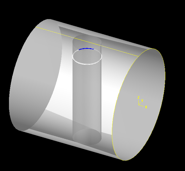
Try In the create menu create curve constant parameter slide the select arrow onto the surface in the hole - it will work with solid faces There are two choices one will give a line along the surface the other will create a geometry as a circle - now just analyze entity properties
-
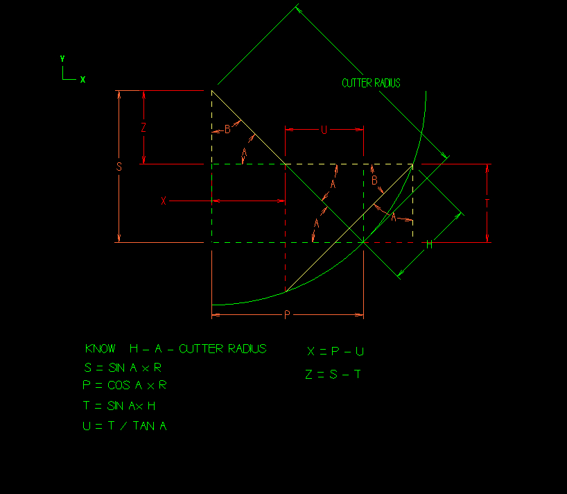
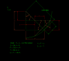
OOPS Formula for T should be T = COS A x H
-
These calculations should allow the X Y and Z offsets for using a ball endmill to cut uniform chamfers The easiest way to do the Z offset is to offset surfaces nad put edge curves on Program the toolpath to the center of the ball endmill It should be possible to write a script to do these calculations automatically
-
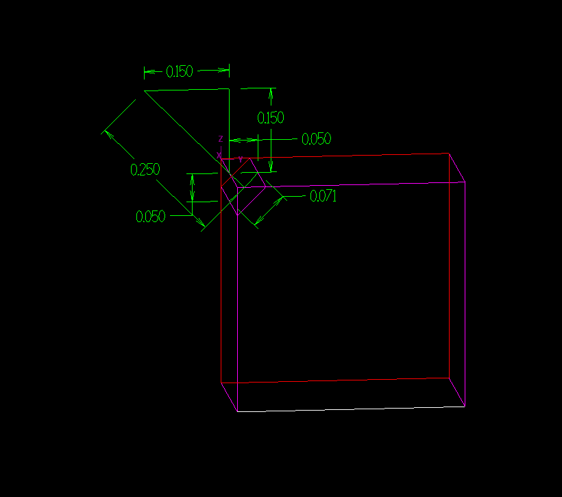
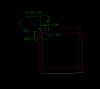
Offset the geometry in the z direction using offset contour Planes will have to be set parallel to each side to get offet to work Then offset this geometry in the xy plane Then program a 3d contour using cutter comp to center of ball end mill The key is that the offset is not the cutter radius but the radius where the cutter contacts the part It is not too difficult to get this number graphically - see the attachment for details I can e-mail you a sample part if you wish - I am not familiar with uploading the files to the web site
-
X5 Axis substitution not drilling all holes I have selected
JDowe replied to JasonM's topic in Industrial Forum
On the point sorting page try turning off "filter out duplicates" -
Lay it out flat - write a mill pocket toolpath - roll it around the dia. If the sides of the tab must be parallel in the veritcal direction then you might have to use roldie - which is a c-hook
-
I think you can run the program and create geometry and toolpaths but you cant save or retrieve any files
-
Is there a way to change the chuck jaw size and location when choosing the Vertical mill with the 4th axis on it? Thanks for any help
-
Is there a tutorial on building machines? What is the process for building a machine? What files are used and where are they located? I would like to get stared building a couple of machines but dont see how to go about it Thanks for any info to help me get started
-
How do I get to the machine build and modify function All the choices seem to be greyed out on my system
-
Help With Toolpath Selection
JDowe replied to Justin Beebe at Folsom Tool's topic in Industrial Forum
Could not get FTP to take the file will e-mail a sample if you want -
setting the part so the hole surface is in the top plane with 0 on the bottom of the part Ball dia = .75 x 2.2813 y.9117 c -20.483 b -57.713 these are the posted values using 5 axis drill parallel to a line through the center of the hole - origin set to tooling ball center
-
Help With Toolpath Selection
JDowe replied to Justin Beebe at Folsom Tool's topic in Industrial Forum
E-mail address? -
Did anyone go to Chicago - what did Mastercam say at the show?
-
Help With Toolpath Selection
JDowe replied to Justin Beebe at Folsom Tool's topic in Industrial Forum
To cut the od try 3d contour this will leave radii in the corners - for the chanfers try swarf to finish the corners maybe surface contours with lines for toolaxis control some geometry needs to be created for this I can e-mail you an example if you want -
Bet they are showing it in Chicago at IMTS
-
My computer does the same thing with translucent set - I dont know why
-
Toolpaths drill select mask on arc Select the hole size arc Put window around all holes this size Hit the enter key - this is what many forget sort the pattern green check mark
-
FBM drill has autmatically found muiltiple hole sizes and set multiple planes for drilling cylinders
-
If your geometry is reasonably clean after raster to vector conversion Try opening up the chaining tolerannce and writing contour toolpaths use tolpath filter then save toolpaths as geometry