


Kyle F
-
Posts
173 -
Joined
-
Last visited
-
Days Won
2
Content Type
Profiles
Forums
Downloads
Store
eMastercam Wiki
Blogs
Gallery
Events
Everything posted by Kyle F
-
I'm definitely interested in this,.. as not too long ago I programmed a 4th axis part that did a bit of simultaneous work (usually it's just 3+1 workflow on our 4th axis) and I had the exact same issue. my rotational axis would spin the wrong way. this was on a haas vf-2 with hrt210 (IIRC) It was just on one toolpath so we ended up just going in and fixing it by hand but it's been on the back of my mind ever since. Anyways best of luck and I'll be looking forward to figuring it out as well.
-
Is this a single contour we are looking at, with multipasses for rough/finish? or are they separate contours, one for rough and one for finish? I am a mill guy but I believe there are a few different ways you could get the movement you're looking for.
-
You are a wizard,.. may I ask how you did that?
-
I am running an NVIDIA Quadro M5000 and now I want an upgrade lol
-
that's a pretty nice flex that you sent them a sample part with the quote. We usually don't even get the 3D model until we've already won our contract which seems crazy off to me as a programmer. I hate quoting based off a print with no model.
-
PREACH brother!!!! this is the story of my life hahaha, having to bust out a threadmill to hit a stupid depth because they didn't leave me any room at the bottom of the threaded hole for a rollform lead smh. Only difference is at my shop we don't charge extra for the dumb stuff, cause it never gets noticed until I'm actually programming it. Then I'll show my manager and ask "how did you expect me to mill that?" and he always replies "oh wow I didn't see that when I quoted it"
-
I'm going to have to take a peek into this arc3d chook,.. I am very unfamiliar (really only ever used findoverlap) but a few of our machines are 20yr old 3axis' that have max memory of 1MB haha so I'm constantly using arc filters.
-
I'm not 100% positive,.. but I wouldn't understand how you could get it to do that. I've never had any issues with feed rate leading in on a thread mill either though,.. I tent to play it safe on the speeds/feeds while thread milling personally anyway. These seem to be the only options on threadmill lead-in/out. but actually,.. now that I'm thinking about it... technically you could draw wireframe in the geometry of your toolpath and you could 3d chain on that,... then for lead in/out you have a box for 'override feed rate' haha so I guess it's possible but IMO the juice ain't worth the squeeze.

-
I am mainly self-taught, aside from a one week multi-axis class that somewhat helped open the door. Youtube, Redditt, and forums have now taught me sooo much more. If my boss ever wants me to go up for any more teaching I'm going to recommend you hahaha. thanks ron
-
some people say it's "extra",.. makes me feel vindicated reading your response! not many things feel nicer than hearing a brand new program of mine had 0 issues.
-
I suppose it could come in handy if you had, let's say, a .275 internal radius that you're dynamically milling with a .5 dia tool, and you were worried about all that tool contact in the corner. typically though if this is a worry of mine I'll just increase the min radius in my dynamic toolpath and address that extra stock in the corner with a separate toolpath with lighter speeds/feeds.
-
MCAM 2024 - takes 5-7 seconds to load tool library
Kyle F replied to Tinger's topic in Industrial Forum
man oh man! the stuff people had to do in the past that was so painstaking,... is now 2-3 mouse clicks.. I am very grateful for the technological advancements in CAM haha that's a metric f-ton of savings -
Defining High Feed End Mills
Kyle F replied to Motorsports-X's topic in Machining, Tools, Cutting & Probing
I only have experience with helical high feed endmills, on their site they have the file available for download that has a 2d wireframe of the tool profile where you just create a custom tool with the geometry from a certain level in mastercam. Since high feed endmills typically have multiple radii on the cutting edge, I'd suggest just getting the .STP or .DXF from tungaloy. (on the tool description page you posted, under "files package" you can apply for said files (weird they wouldn't just give them lol)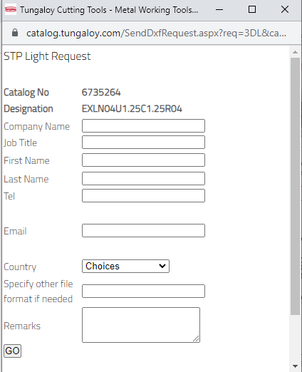
-
MCAM 2024 - takes 5-7 seconds to load tool library
Kyle F replied to Tinger's topic in Industrial Forum
this is my situation exactly. At work it takes about 5-10 seconds to pull up (still on a network, but local). then when I'm programming from home, it has to go through the VPN and the network,.. it takes about 30-45 seconds... this is when I lurk the forum hahaha. that, and when annoying stock models are regenerating. -
Okay, I appreciate the clarification. So that was exactly as I had my tool setup, but once I imported geometry from a level, when the pop-up box asked if I wanted to override the previous blah blah, I said yes. So this time, I hit no, and voila! it worked. Thanks again, now everything is showing up perfect Excellent info! I love it. and I am not opposed to a zig zag pattern for the finish, my only worry is, I have never used a HSS convex radius cutter like this (only smaller carbide keyway tools from something like harvey tool) and I'm a little curious on how it would do in a conventional cut. sorry to get so deep into the weeds on this one haha

-
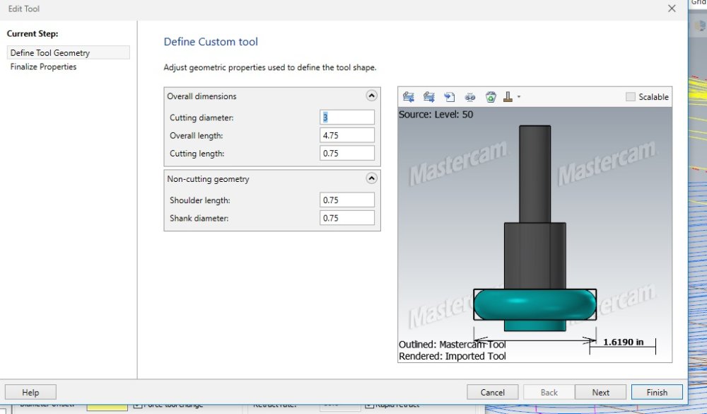
Both the left and right cutters in my previous reply were created as slot tools. only originally was I trying it as a custom tool. Only difference was after I created the slot tool, I then linked geometry from a level. Since the bottom section (arbor cap) wasn't set as cutter geometry I figured maybe mastercam would ignore it but that doesn't seem to be the case. I wonder how you could leave the cap simulated, but still perform these surface finishing toolpaths? if in the future the geometry wasn't so forgiving and I actually had to worry about the clearance. thank you for all your help, and I hope I'm coming across clear enough. wooooowww I love this forum haha, I always create a separate model, then model prep push/pull certain areas, then create surfaces from that solid, then chain to those surfaces,.. you just saved me a ton of future work, thank you. this is also a great tip, I'll be fidgeting with these settings to see what kind of lead in/out I prefer. Thanks!
-
I have found the issue! so I tried flowline like you posted and it still wasn't quite working out,.. which led me to try and re-create my slot tool (again lol) this time I didn't link to any custom level geometry, so it's essentially the same except when I don't have the arbor cap drawn, it cuts correctly. quite odd but something with that geometry hanging off the bottom of the radius cutter, masetercam doesn't like it for my toolpath. I'll just extra careful when proving out the program in the simulator to ensure the cap won't collide with anything, this shape is simple enough it shouldn't be an issue.

-
I'll give this a shot for the finish pass and see how that goes. thanks for your input.
-
Thank you so much, I'll give that a try. and by the way ron, I really appreciate you and all the interview/video content you've helped to create on youtube. It has helped me a ton! I've been a lurker on the forum for a while lol
-
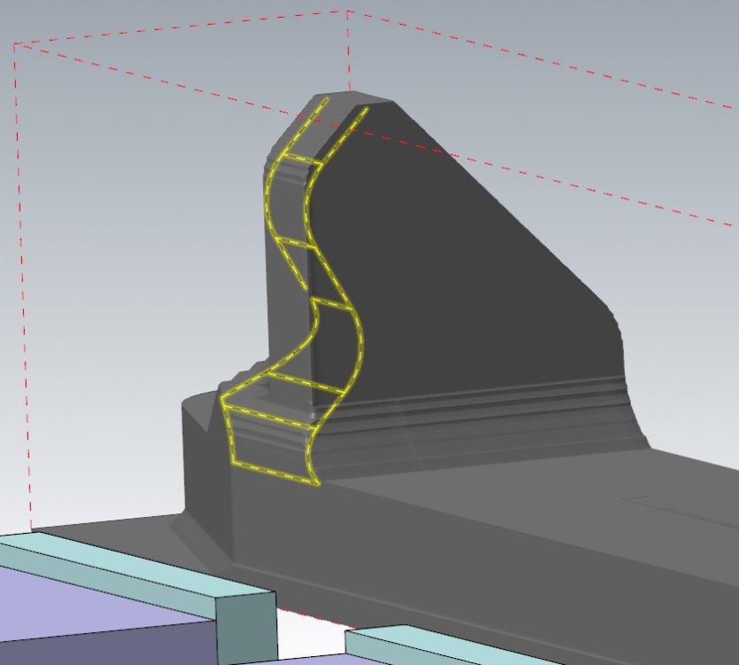
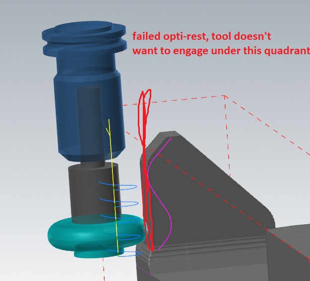
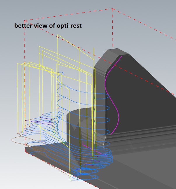
Hello everyone, I'm having some trouble with a project I'm currently working on. I'll attach some screenshots to further explain my issue, but long story short I have a full radius saw blade in an arbor + hardholder. I just drew wireframe on a separate level and linked that geometry to create my custom tool. I have a full multi-axis license but this job will be on one of our 3 axis mills. Essentially I roughed the part with a shellmill and now I need to address the undercut sections, where I plan on roughing + finishing with this full radius saw cutter (aluminum). Ideally I'd like to rough this area with an opti-rest but I just can't get the toolpath to mill the undercut section. I also have tried a few different surface finish toolpaths for the finish passes but all to no avail,.. this leads me to believe maybe my issue is in my tool definition, should I maybe try to create the tool as a slot mill instead of custom tool? the geometry of the undercut is pretty simple so I'm not too worried about the opti-rest failure because I could always just have a few seperate contours of various depths/multi-passes to rough, but I would really mainly like to get the surface finish figured out because programming that "manually/old school way" is definitely possible but certainly a pain in the butt lol. I appreciate any feedback or help!
-
That's really impressive. Can you give any information on what you changed in the re-programming process to help the part from distorting?
-
hehe edm you say? I'd probably take it to a grinding wheel in the back by hand LOL gotta do what you gotta do, great idea.


