CJep
-
Posts
1,593 -
Joined
-
Last visited
Content Type
Profiles
Forums
Downloads
Store
eMastercam Wiki
Blogs
Gallery
Events
Everything posted by CJep
-
What exactly are you looking for? It's the blend tpath in the HSpeed format so it adds the surface selection utility, gouge check strategies, hspeed linking functions
-
Yes there is a HSpeed version of the blend tpath If you right click in the operations manager you'll see all the mill tpaths were as there is a limited view in the dropdowns The blend tpath in the dropdown opens the new tpath interface, to get to the legacy blend you need to open the tpaths from the operations manager
-
Won't post entire group of toolpaths into one file
CJep replied to NickMyles's topic in Industrial Forum
double check the NC file name to fix it select all yer tpaths, right click in the operation manager (where all the tpaths reside) and select edit selected operations, change NC file name then try to repost- 8 replies
-
- 1
-

-
- post
- post problem
- (and 1 more)
-
why does raster rise and fall next to walls?
CJep replied to lowcountrycamo's topic in Industrial Forum
semantics you know what I was sayin -
why does raster rise and fall next to walls?
CJep replied to lowcountrycamo's topic in Industrial Forum
Avoidance surfaces are used in the newer format High Speed surface toolpaths, they are essentially check surfaces similar to what were used in the legacy surface tpaths. However you can have multiple avoidance surface groups selected with different values for stock to leave. In the HSpeed surface tapths you can also have multiple machining surface groups selected with independent stock to leave values as well The issue with Low Country's part file of the tool climbing up the wall was corrected by eliminating the avoidance surfaces and changing the control method to a containment boundary. It all has to do with how the tpath is looking at the geom and how it effects the math, there was something about those surfaces that required the tpath to do a retract. Remove the offending surfs, retract is gone, need to find a different method of controlling the tpath along the edges. -
Creating static & live tool holders for lathe
CJep replied to MetalSlinger5's topic in Industrial Forum
Ifen you're working with mcam 2019 or 2020 you can use the create 3D tool utility in the lathe tool manager -
OP your machine def got hosed. I would start with a new copy of a working machine def
-
why does raster rise and fall next to walls?
CJep replied to lowcountrycamo's topic in Industrial Forum
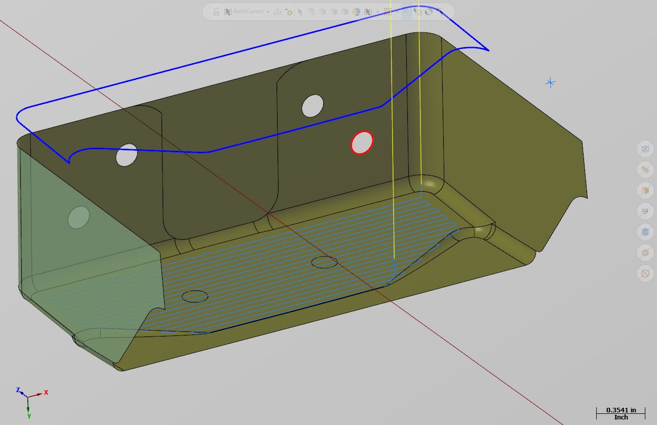
It was associated to the avoidance surfaces. Changed the method of control to containment boundary, reset the step over to clean up a move at the end, set the keep tool down to 50% the tool dia, fixed a couple surface normals and changed the surface color cause the orange wasn't working for me. raster wall climb_CJep.mcam
-
didn't say it were perfect yes to do simultaneous 4 he would need a multiaxis license I just threw a tpath at the geom while I was waiting fer another tpath to regenerate Edit: added Swarf tpath SLOT_CJep.mcam
-
Axis Sub sample SLOT_CJep.mcam
-
that is axis substitution, you could use a contour then set the rotary control to wrap the geom around a dia can you put up a file
-
the only dumb question is the one left un-asked,.. The machining region in the sample file is the stock boundary, if nothing is selected with regard to geom it will revert to the stock When setting up a machining boundary for an oddly shaped part say a forging or casting then you need to create boundary to define the shape. I have attached another sample using an offset boundary. The red is the finished part geom and the green defining the shape of the stock I'm starting with, the solid model on level 14 was used to define the stock for Verify. 2D HSpeed -w- Remachine_02.mcam
-
This has a bit more to do with the tpath you started with and how you're defining your stock In the attached sample file I have two different types of tpaths the stock has been defined as a rectangular block. Notice when the 2D HSpeed contour is run the tool starts in the material. This due to that tpath following a contour that is defining what is to be machined. In the 2D Dynamic mill tpaths the stock boundary is being use for the machining region and the part geom is selected as the avoidance region, now the roughing tpath starts outside of the stock and collapses on to the part geom. The remachining tpath is a copy of the roughing tpath with the rest material activated and the tool changed out for a 1/4" dia emill 2D HSpeed -w- Remachine.mcam
-
do you have multi-passes turned on using both a roughing and finishing passes make certain you have "machine finish after roughing" turned off and set the multipass to "by contour"
-
can you do a file save some and only save the geom associated to the tpath
-
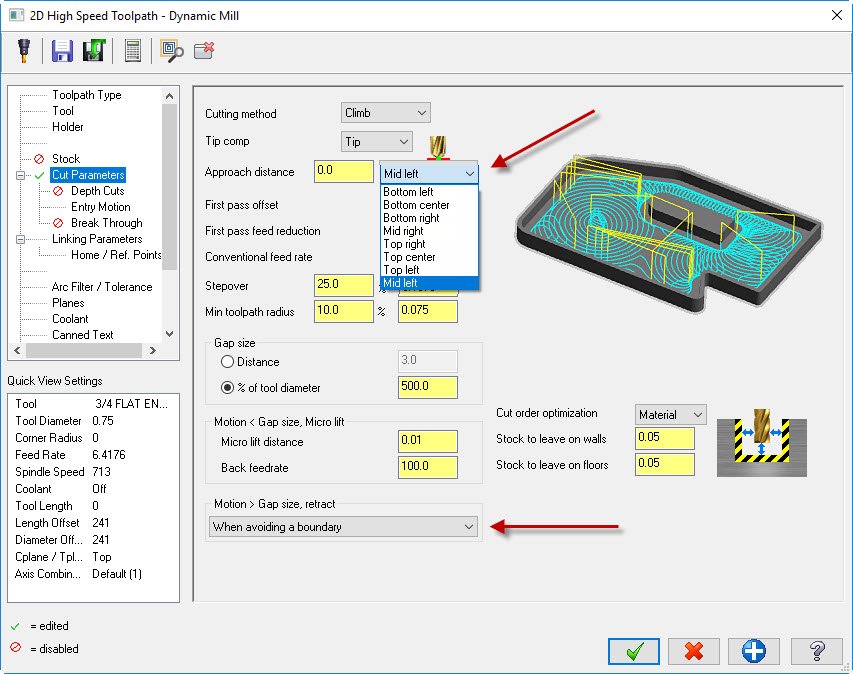
you can change the bias of were the tpath starts by using the approach drop down, you can change the retracts by setting the motion<gap size, retract
-
Dynamic contour is not setup to do remachining, it's a constant engagement finishing tpath 2D Dynamic HSpeed is a constant engagement roughing tpath, ifen you're looking to setup a restmill op yah gotta go with that tpath The reason for offsetting the contour is to give the 2D Dynamic HSpeed the correct parameters to run the algorithm, it requires a machining boundary Ifen you don't care to use a HSpeed tpath you can turn a legacy 2D contour into a remachining tpath using the contour type drop down on the cut parameters page
-
Instead of using the Dynamic Contour for the 1/4 dia tool, use the 2d Dynamic HSpeed You will need to create a machining boundary, you can offset the existing contour slightly more than the tool dia. By using the 2D HSpeed you will be able to activate the rest mill function using the stock utility. Select the offset chain as the machining boundary, don't forget to use from outside for the strategy and use the finished profile as the avoidance region. In the stock utility select the previous HSpeed contour to run the rest mill against.
-
When in Rome,.. Autosave - no Backups - yes set to 5 max, mapped to secondary drive Save - yes often, hot key Ctrl+S
-
double check yer post, make certain you don't have an "N$" in front of the "comment$" another place you can check is in the "pcomment$" section, make certain there are no "N$" in front of "scomm$"
-
The preferable location for the documents files are the local C drive of the Mcam computer both the user and public, when folks try to redirect to a different location chit gets weird
-
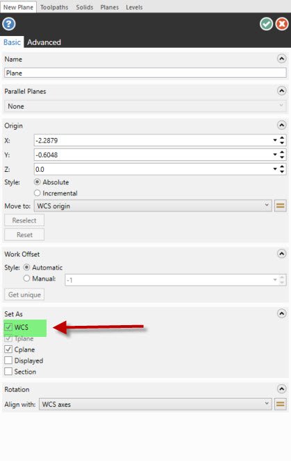
If you're using the dynamic planes utility to create custom planes double check the "Set As" check boxes Set as WCS is checked by default in a fresh session of Mcam, if you turn it off the first time you use the utility it will remember the last condition
-
it's a know issue, it has to do with the math engine they started using in Mcam 2018, you do not have control of the output as a user, as long as you type the correct value in the field the geom will be moved or copied to that position
-
It's not so much the tools but the tool holders, like the blocks that allow you to partial index the turret. There are standard holders in the gmd file however to add a solid model that was downloaded from a manufacture then it takes some work to prep the file and load it into the gmd.
-
Wholly crap, you went from Mcam V9 to Mcam 2018? That's like working with a different program. sorry Rodger: off topic swerve