Newbeeee™
-
Posts
3,421 -
Joined
-
Last visited
-
Days Won
40
Content Type
Profiles
Forums
Downloads
Store
eMastercam Wiki
Blogs
Gallery
Events
Everything posted by Newbeeee™
-
This
-
The whole WCS/Planes "thing" is the biggest item to get ones head around (learn) in mcam IMHO, especially when talking 4axis. I'm sure it was Motorcity Minion who posted a great "how to" word doc back in the day. I put together a pretty comprehensive enhancement request and was then told the whole planes (and manager etc) was getting looked at and a makeover. This was X7....
-
That was another enhancement request back around X5 (2012?) - if we can't delete, can we append the name, so TOP could become "TOP (OP1)" and "BOTTOM (OP2)" for example. It was met with all-round positivity, so naturally went to the bottom of the pile
-
Ohhhhh, blame me. Go on, why not. It's ALWAYS my fault....
-
^^^TBF, is that V9 or 2020?
-
Being UK we used Control 100% for finishing paths. By the time I read about wear, we had a load of new progs and Bus.Partner wasn't happy about changing as he never saw the benefit But the lead-in-out I set to 55% default. I'm sure initially, it was 50% but on a part (or two) we got the fanuc comp alarm. 55% cured it and we never had a problem again.
-
Wanted: Old Mastercam versions... V2, V3, V4
Newbeeee™ replied to mark casella_1838's topic in Industrial Forum
Intrigued to know your plan....Will you fire up the PC and show someone the SW when they visit? And hope that the PC will fire up, and hoping someone will be able to remember how to drive the SW? IDA thought it farrrr easier, to screen record a few bits of a demo and then you can run that on any screen/PC you want? -
Is this because....basically....under the hood....it's still the same?
-
What I did with my Robos, and all my Fanuc machines:- Parameter 1401:- change bit Rapid linear/Rapid non linear Also changed the bit so when the Feed override knob is "0", the rapid does not move when the rapid knob is "0". Default, all my machines would creep, when Rapid was "0" (so "0", wasn't "0"). Then parameter 1421:- changed this to be 400 (mm/min) So when proving a part, with rapid override at "0", the axes still move when rapid is commanded and the feed override is above zero. Then to stop the rapid, wind the feed override to "0". I chose 400mm/min as that was a suitably low rate that my reflexes would be able to react to if something didn't look right
-
Big shout out to the Rubert company! During my apprenticeship I decided surface finish was going to be the subject of a thesis....so I contacted them for info and they supplied lots and also a FOC Rubert chart that the photo shows. I even saw them today in my toolbox
-
Do you prefer Stock Models or .STLs for use in Mastercam.
Newbeeee™ replied to [email protected]'s topic in Industrial Forum
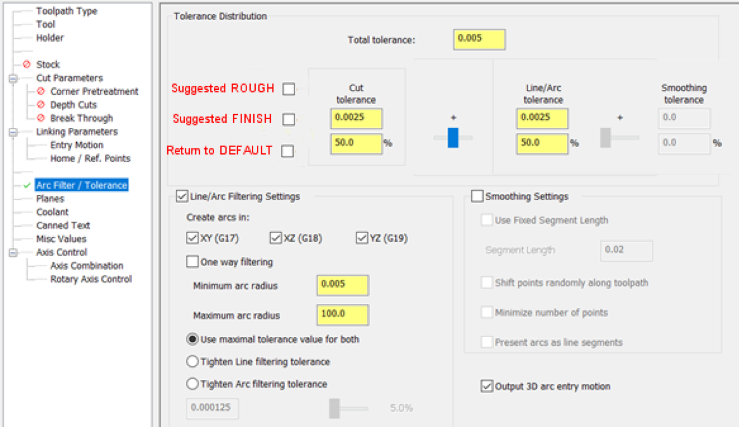
Since the introduction of stock models, I always thought that the filter setting would benefit from having the below screenshot:- Mcam default values for both rough and finish, together with a "return to default" incase of too much blind fiddling This would be better to be settable - user defined and saveable. I'm sure it was Colin ( @Colin Gilchrist ) who did a great write up explaining the settings a few years ago (I know you have explained it in the past too), but I bet 90+% of "programmers" don't even touch the defaults and wouldn't know where to start. Disclaimer (!) I realize that we all do different types of work and some people love doing stupid tight work that the majority of us would no-bid (sit down Ronaldo ) but is it fair to say the majority of users do a "certain/normal" (to them) type of product line, that for the majority of their parts, defaults could be set (and certainly roughing defaults)?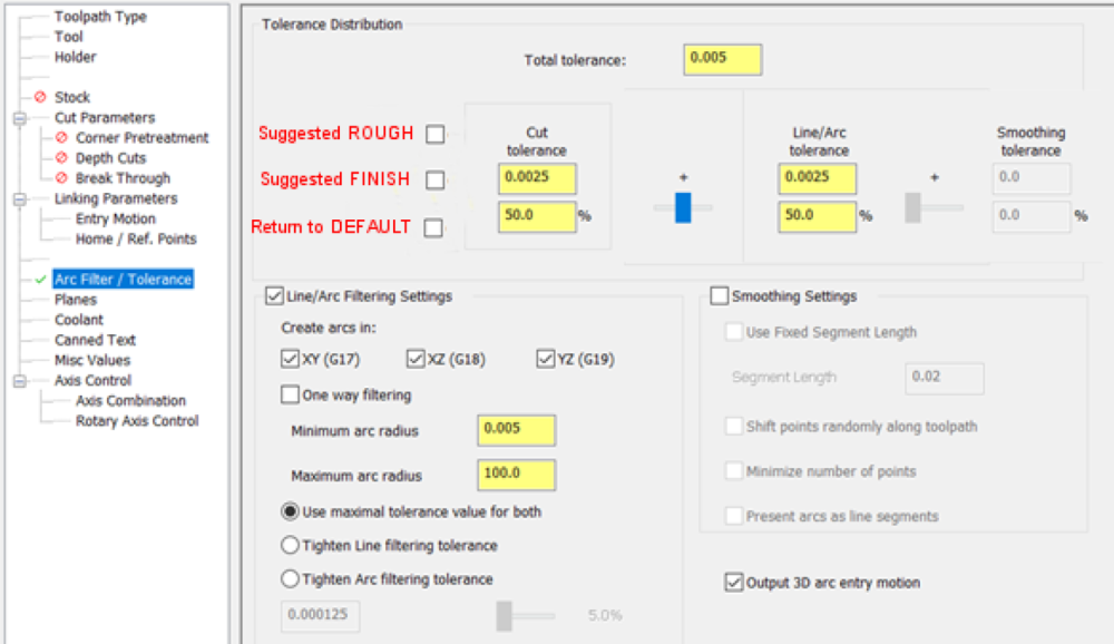
- 29 replies
-
- 5
-

-
- .stl
- stock model
- (and 4 more)
-
I would always use the one-click magic rough button (optirough) for all roughing and then occasionally semi-finish with it too. Then for finishing, everything would be wireframe for all the reasons the guys said above - but predominantly lead in and offs etc. The vast majority of my stuff was electrical enclosure type parts so prismatics (2D ramp contour for sidewalls and pocket for bottom) , but when there were scanned faces, copy surface and untrim/extend to allow for lead in/out using the fantastico flowline. I tried to love the other paths but gave up with the roll over of the edges (what is THAT all about )
-
Jakey - you're new here. Don't overthink this too much.... I had plenty of enhancement requests that were "looking to be implemented" back in the X5/X7 days, and only a couple made it. Since then, adding clicks has been the goal - not reducing them!
-
Change ALL machine parameters to be identical. Remove doglegs from them all. NOTHING is worse, than one machine (or when a new machine lands) and it's configured differently to the rest. As for this comment (and I see someone LoL's at it) - IMHO, this is very true. I got bit by one of my new (at the time) Feeler drill/taps with 60m rapids. Fanuc Alpha pack model D. Electrical enclosure that would fit in my hand with straight sidewalls and profiled internal tapped lugs and bosses - ran 1st part 25% rapid and got first off. Ran second part at 50% while on another machine and heard a "ding" resonate for a split second. Didn't notice anything on the part. Ran third part at 100% and there was a very loud "ding". What happened was the rapid retract was well below the top surface of the component, and the tool simultaneously retracted up moving to the start position of the next feature - clipped a lug, putting a 1mm x 45degreeish gouge at 100% and scrapping the part. The 50% would buff out (0.2x 45degree deburr LoL) and the 25% was only just visible. Long short the machine at those rapid rates/acc/dec had a LOT of following error, and there is/was no parameter to change to keep rapid following a more accurate path. This was in G05.1 lookahead. So yes - from that day forth....I always rapided (rapidid?) (rabid ) to a clearance above the top of the part. Back to the OP....Brother could be the same. Rapido rapids and the following error might be biting you too?
-
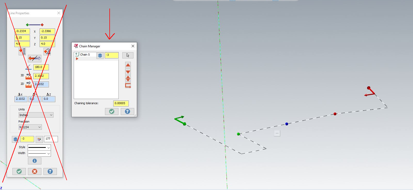
Yes - I'm suggesting keep the existing way untouched, but in the vacant space of the chain manager, the level of the chain could always be shown. So for OP's request - the data is there and no more clicks need to happen. I should have been a bit more clear but wifey shouted "grub's up"
-
Enhancement request!!!

-
Simulation: current simulation is still discarding -2019
Newbeeee™ replied to mittler's topic in Industrial Forum
Post 2 and 10 seem to nail it. There's a timing issue there "somewhere"....and reboot obviously resets/sorts it. Until the next time.... Hence Crazy's Q's which are all very logical. Networks (amongst other things) can kill with delays etc.... -
Torque Wrenches for Production
Newbeeee™ replied to Jobnt's topic in Machining, Tools, Cutting & Probing
So I dug back and checked....CP was the name as I remembered the logo! Chigao Pneumatic. It was easy(ish) as we did ground up turnkey of everything....so standardisation to M8 was easy. We used these and regulated the air input. Set the setting on max and it worked out well for M8. https://tools.cp.com/en/products/impactwrenches/cp7721 For you, the biggest battle obviously is operator "forgetting" to use a torque wrench. Genuine "forget", or "can't be bothered as it's tight" forget? Looking at your thread sizes (6.35 + 12.7), M8 sits right between but I appreciate changing things over is a big project. But if you can, it's once and forever. Where "forgetting to use the torque wrench" will possibly be forever? Could you do one cell at a time, and use screwed air fittings rather than quick release to stop anyone easily swapping out the gun etc? Just thinking out loud. -
Torque Wrenches for Production
Newbeeee™ replied to Jobnt's topic in Machining, Tools, Cutting & Probing
One Customer of mine - we standardised all fixings to M8 Skt Cap screws and used a small body (low power) butterfly type. If you have various size threads I think you'll be on a hiding to nothing because (IME) the boys will leave it set at max torque.... -
If cut tapping...you need bright (uncoated) finish tap. Clocked in to run zero runout. Spiral point tap geometry (which is stronger and will push the swarf through). Faster RPM - 1500 minimum. Coolant strength at 10%. But preferably, roll tap it....
-
I had put an enhancement request in wayyyy back in the day, to split out trim/divide so I could have an individual (separate) mapped key for the one operation. So any pain, gripes and general dislike can be thrown my way. I have broad shoulders
-
Holymoly. So they're still not updating master posts and all the meetings etc were for nothing. What a shambles
-
Sorry to have heard this Ron. May your Dad RIP.
-
Yes that's correct. The turrets have Sankyo name on them but are made by Sandex (same manufacturer as for the milling machine toolchanger camboxes). They have a servo drive with encoder to give position, and a cam slot for the index, with needle roller bearings running in the cam slot. We had (allegedly but not sure) insert go on a boring bar which was deep into a 2.5" billet and it caused the billet to eject from the soft jaws. Apparently. Anyway, the billet definitely came out....resulting damage was the needle roller exploded in the slot which dented the cam slot, which because there was no hirth/clamping, we had float on that turret position for ever more. Not much, and as it was radial float (about 5 thou), it didn't affect the diameter/size, so we used that as a permanent rough pocket going forwards. Other damage was the Z rails needed replacing - if you look at the machine design, and see where your tool is in contact to the work, follow it up and back over to the roof of the machine - there is a HUGE amount of mechanical advantage (leverage) from tool tip upto the Z rails. Hence them getting "dented" in the crash. So treat it with care and it will do some good work. Treat it as a robust heavy duty mill-turn, and you'll snap it in half!
-
Yes - Reading the comments I was going to add that machine models didn't just have Yasnac, but also Mitsubishi as well as others with Fanuc back ends. All front ends were Hitachi own proprietary software written by their own sub-contracted software house. You're lucky having Mitsubishi as yasnac support is next to useless. Don't bang the machine as the turret has a roller cam box with no positional clamping....the Z rails are up and over running on the roof of the machine and if you have a smack, these can be taken out too. Also the Y axis rails are about 12mm wide..... Treat it gently and they work well - trochoidal tool paths for any milling is advised as 12mm dia is a large cutter which is great for making "grippy surfaces" but not so good if you want to cut a good finish.... :)