Scott Lundin Shopware Inc.
-
Posts
538 -
Joined
-
Last visited
Content Type
Profiles
Forums
Downloads
Store
eMastercam Wiki
Blogs
Gallery
Events
Everything posted by Scott Lundin Shopware Inc.
-
Rolldie help!
Scott Lundin Shopware Inc. replied to Richard Thomas - Mastercam UK's topic in Industrial Forum
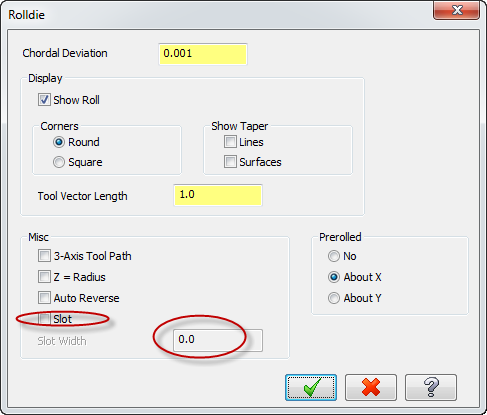
I do remember reading somewhere that if you use the slot option in roll die the walls will be parallel to the center line (walls not pointing to center). I will have to look around and see if I can find the documentation.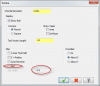
-
Rolldie help!
Scott Lundin Shopware Inc. replied to Richard Thomas - Mastercam UK's topic in Industrial Forum
Here is a roll die file that won't work because walls are not pointing to center. ROLLDIE-NOT.MCX-6 -
Rolldie help!
Scott Lundin Shopware Inc. replied to Richard Thomas - Mastercam UK's topic in Industrial Forum
Here is roll die file that works with walls pointing to center line. ROLLDIE_90-DEGREES_FIN_GOOD.MCX-6 -
Rolldie help!
Scott Lundin Shopware Inc. replied to Richard Thomas - Mastercam UK's topic in Industrial Forum
Rich, From my experience with roll die, it only works if the walls of the pocket are pointing towards center line. In all other cases I have had to use swarf or one of the other multi-axis paths. -
Are you drawing and chaining the geometry above centerline or below? Should be above.
-
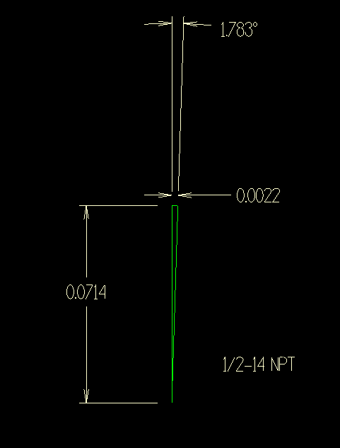
Even if your tool has enough teeth vertically to cut the tapered thread in one circular move around the hole you should still set the taper angle. For a 1/2-14 NPT with 1.783 degree taper, the tool would rise .0714 in. in the Z-axis during one circular move around the hole. This would be a difference of .0022 in the X-axis assuming you started and ended at 3:00. Look at your output g-code, the X and Y moves should be expanding outward as the tool feeds upwards.
-
If you chain a point it will drill towards center line. You need to chain a circle so it will rotate the spindle to the correct plane and drill what you are looking for. A circle always lays in a flat plane so this is how mastercam knows to rotate to a plane and shift up or down in Y.
-
mastercam x7 won't let me modify parameters
Scott Lundin Shopware Inc. replied to pcpoirier's topic in Industrial Forum
Are you using the same machine type on both computers? Different machine types will have different fields grayed out and not usable. -
Some readers may be wondering why you would want to have tangent lines and arcs rather that splines. One reason is that the "wireframe 2D swept" tool path does not allow the use of splines. What else are you guys using this type of geometry for?
-
Coolant Filtering
Scott Lundin Shopware Inc. replied to BrianP.'s topic in Machining, Tools, Cutting & Probing
Also if the coolant is already saturated with oil nothing will bring it back. Its best to start out by cleaning out the tank with a proper sump cleaning agent from a coolant vendor and putting in a fresh charge of coolant. Then maintain a good oil removal process on a daily basis to keep most of the tramp way oil out. -
Coolant Filtering
Scott Lundin Shopware Inc. replied to BrianP.'s topic in Machining, Tools, Cutting & Probing
The stink is caused by bacteria. Bacteria eats tramp oil for breakfast and the stink you smell is their waste product. Keep the oil out and they have nothing to eat. Also if the oil is turbulent it slows down their reproduction. The Zebra coalescer mentioned in an earlier thread works great if you know how to use them properly. On week nights I would let the Zebra run all night while the machines were not running. On weekends I had an air regulator with a perforated hose/pipe that I would slip into the coolant tank and let low air pressure bubble the coolant to keep it moving. I was able to keep the same coolant in the tank for over a year this way. Of course you have to add some as it gets low. Do not use bleach or anti-stink chemicals, this = backyard chemist. -
X7 tool manager column defaults
Scott Lundin Shopware Inc. replied to Cannon's topic in Industrial Forum
You can do this in the tool manager window as well. -
X7 tool manager column defaults
Scott Lundin Shopware Inc. replied to Cannon's topic in Industrial Forum
Here is a screen shot of my tool filter layout.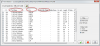
-
X7 tool manager column defaults
Scott Lundin Shopware Inc. replied to Cannon's topic in Industrial Forum
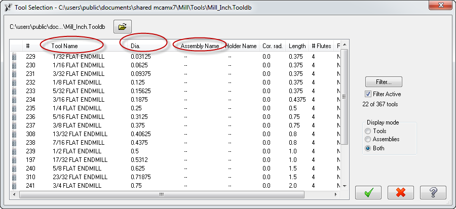
I have sent this "tool vs. both" request into QC a couple times now. In the mean time you can drag the assembly header name over so the toolname and diameter column are right next to each other and widen them out. This does stick for the next time. -
Nedd Help getting X7 verify not to Crash
Scott Lundin Shopware Inc. replied to Rstewart's topic in Industrial Forum
I use Microsoft Security Essentials on all of our classroom computers and do not have any issues with Mastercam. This is not the problem. -
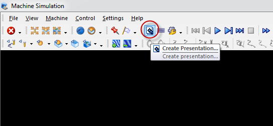
Or, use machine sim. You can have it create a presentation file that you can email out. Recipients do not need to have mastercam to view it. They can zoom pan rotate, etc.

-
Modify lathe.set file for X6
Scott Lundin Shopware Inc. replied to Scott Lundin Shopware Inc.'s topic in Industrial Forum
My mistake. What you said does work. I must have forgotten to hit save before exiting out of the modification. -
Modify lathe.set file for X6
Scott Lundin Shopware Inc. replied to Scott Lundin Shopware Inc.'s topic in Industrial Forum
That did not work. Would have something to do with this other line? fs2 4 0.2 0.2n #Decimal, absolute, 2 place, non-modal fmt 4 absfr #Feedrate -
Can someone please show which lines of code would need to be changed to get the setup sheet from lathe.set (X6) to output a 4 place decimal for the feedrate? It currently only outputs 2 decimal places. The lathe.set file can be found in your sharedmcamx6\lathe\posts folder.
-
Bottom Right corner of the editor window there is a slider bar for font size.
-
Stock Defined In Both Spindles
Scott Lundin Shopware Inc. replied to Mick's topic in Industrial Forum
To get around this problem in X6 I always used to move the red insertion arrow up above the stock transfer operation prior to deleting it. I have not tried it in X7 yet. -
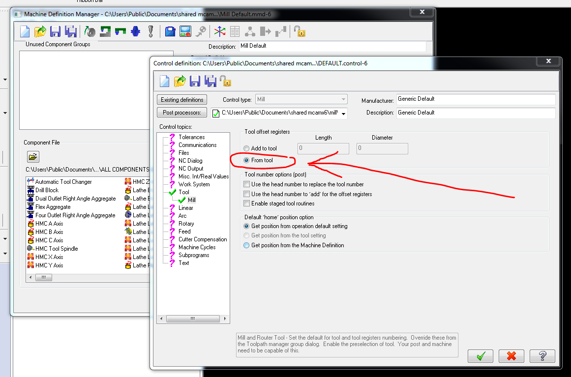
Retaining H and D values from library
Scott Lundin Shopware Inc. replied to cincy k's topic in Industrial Forum
Set your control def to "from tool" as shown in attached picture.
-
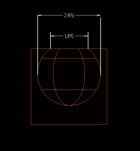
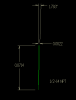
Making impressions in a block ect?
Scott Lundin Shopware Inc. replied to Gary's topic in Industrial Forum
Maybe this needs a little more clarification. My attached picture shows a Mastercam Boolean Remove using a solid square block and a solid sphere. So do you mean that you want it show the 2.496 dimension straight up to the top of the block ignoring the 1.495 shape/dim?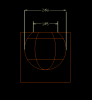
-
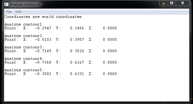
List of point coordinates
Scott Lundin Shopware Inc. replied to Bill Cronkhite's topic in Industrial Forum
You can even open the txt file generated by analyze contour and it will bring in all the points as Colin mentioned. I did not expect this because of all the extra text in the file. I guess it just ignores that extra stuff. -
List of point coordinates
Scott Lundin Shopware Inc. replied to Bill Cronkhite's topic in Industrial Forum
Another way to get a list of the point coordinates is to use 'analyze contour", window chain the points, pick a search point, OK the chaining box, OK the analyze contour box, and then save the listed points as a txt file.