


Reko
-
Posts
909 -
Joined
-
Last visited
-
Days Won
30
Content Type
Profiles
Forums
Downloads
Store
eMastercam Wiki
Blogs
Gallery
Events
Everything posted by Reko
-
I think you need to go into the Operation Defaults... set it there.
-
It should be in the "Control Definition" under "Tool"...click "Add to Tool" and put zeros in the length and diameter boxes.
-
InHouse Solutions post here... about a half-dozen tweaks at around a week per request. I assume they implement them into their main version, so if you get this post from them it should be pretty solid.
-
True... I just meant you can change any value in the middle of a canned cycle by putting the new change on any line you want it to change, then everything after that continues at that new value.
-
No problem. You can also change them on the fly too... need a Z depth changed... or an R plane... or a peck... just change it on the line you want and all subsequent lines will follow. G83 Z-1. R.1 Q.1 F5. X0 Y0 X1.0 X2.0 R.25 <-------------- X3. X4. Q.08 <------------ X5. X6. F2. <----------- G80
-
Dang it... I can't believe I missed that! Oh well, at least I brought you two old mates together for a chat. Thanks guys!
-
Anyone else seen this in MC2018? If you have a 4 axis post... where do you change from 360 max degree output to Continuous?
-
No they're modal.
-
I agree. This is such a quick and easy option... I sure would like to master it, but you're right... this has bitten me twice now... better to be certain than wreck a third part. I'm going to play with it a bit at the end of this run... I'll try to post up any answers I come up with for future reference.
-
I went into the Machine Def in Mastercam 2018 to change the A-axis setting from 0-360 degrees to continuous... but the tree does not have the A-axis in Mastercam 2018. I checked and it was there in 2017... I did a normal migration, so I don't think I messed anything up... did they put the settings from the tree somewhere else in 2018?
-
I can't test it yet... but... that was set up to a feedrate with minimum retract... if I set it to full retract, it looks like this... do you think this will work? Or... should I set the control def up for feed moves and no rapid moves at all?
-
Here's a pic of the toolpath that violates the part... both Verify and the Machine Sim show no collisions. It is a waterline path with the holder collision set to "Tip to Avoid Gouge"... I also have it set to minimum retract with a feedrate of 500ipm... but look at the rapid lines... they only retract in strange ways staying down inside the pocket... a few of them even curve... I've never noticed a rapid line curve before. I wonder if that could be the problem? I'll test it at the end of this run.
-
Great suggestions... I'm moving on a bit to get this hot job going forward... but there is a scrap part I will test at the end of the run. Using your vector suggestion, I spotted something strange... I'll post up a few pics after lunch. Thanks again guys!
-
"Holder" "Collision Checking"... using a Haas UMC750 with an InHouse Solutions post. Anyone use this? I have tried twice now and both times it gouged my part... it follows the part very closely... then makes sudden moves to violate the solid. It seems like a nice feature... I can choke up on the tool, use a standard 3D path like waterline... then click this to tip to avoid the holder... sounds easy... doesn't work though. It looks good in verify... doesn't work in practice. I'm just wondering if I need to do something special... or perhaps it is a post problem... or if anyone has had any success with this... or if it has never worked at all?
-
It's Batman... you can tell by his avatar.
-
Under the "Home" tab... above "Display" section... toggle "Arc Center Points."
-
Very cool... would you mind sharing the code/logic for that?
-
Under "Entity Type" I like to use points and lines... when you use "Hole Axis" it gives the option of points top/bottom/both... I put the points on the bottom, then when you select the points under "Entity Type" the line direction from the points controls the vector.
- 7 replies
-
- 1
-

-
- multi axis
- 5 axis
- (and 2 more)
-
I looked through a dozen pages of the pinned X+ discussion page... I don't see anyone crashing. Any chance you can install X+ on a difference computer and test it on the same file? Or perhaps re-download and uninstall, re-install X+? It doesn't seem like you'd get a crash from a particular tool being used. So strange.
-
Yes, I had a problem with it crashing. Updating my video card driver solved it for me.
-
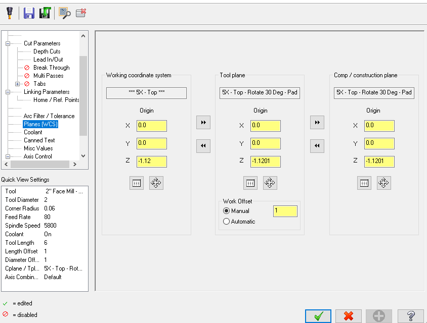
Solution for anyone else looking at this thread... I gave this plane its own offset number and made the rotation at the machine.
-
Okay, that's what I'm getting. Thanks Colin.
-
Thanks for the suggestions Leon82. I played with those a bit... it doesn't look like it affects the "B" axis output at all.
-
Working with a Haas 5-Axis trunnion... I have an over-travel in the Y- axis... so I want to rotate the platter ( B-Axis ) 30 degrees so I can reach the pad beyond my "Y" travel. I've never needed to force a particular angle for the "B" axis platter only before so this is a new problem for me... but when I create a new plane for a 30 degree rotation... the post still outputs A0 B0 no matter what. The Misc-Integers can flip a toolpath 180 degrees from front to back... but it doesn't affect an angle change like this. Has anyone ever attempted this, or had the same problem? Thanks in advance!
-
Brilliant!

